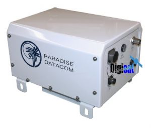
Teledyne Paradise Datacom 7RU C-Band High Density SSPA

Built-in 1:1 Redundancy Control, fully hot swappable power supply system
7RU C-Band Indoor Rack Mount High Density Solid State Power Amplifier
The Teledyne Paradise Datacom 7RU Indoor, C-Band High Power Rack Mount series of SSPAs represent the industry’s highest power density and most reliable high power amplifier systems.
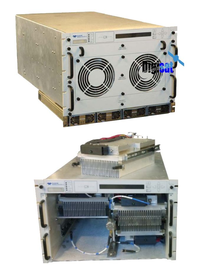
Modular Design
The High Power Rack Mount SSPA employs a modular design, which allows quick and easy replacement in the event of a catastrophic failure of one of the SSPA components. These modular assemblies include: hot-swap SSPA modules, front and rear fan trays; and a rear panel controller card. These amplifiers are powered via a separate power supply chassis.

The power supply is configured as a n+1 redundant, hot swappable, power supply comprised of four modules. Only three modules are required to operate the HPA, therefore one module is redundant. In the event of a power supply module failure, the amplifier system will not fail. The module can then be changed without ever taking the HPA out of service.
Paradise 7RU SSPA frequency plans
|
Band |
Frequency Band |
IF Input |
LO Frequency |
RF Output |
Gain Change |
|
C |
Standard C-Band |
950 - 1525 MHz |
4.900 GHz |
5.850 - 6.425 GHz |
0-4 dB |
|
C |
Extended C-Band |
950 - 1825 MHz |
4.900 GHz |
5.850 - 6.725 GHz |
0-4 dB |
|
C |
Palapa Band |
950 - 1250 MHz |
5.475 GHz |
6.425 - 6.725 GHz |
0-4 dB |
|
C |
Insat Band |
950 - 1250 MHz |
5.775 GHz |
6.725 - 7.025 GHz |
0-4 dB |
|
C |
Extended C-Band 2 |
950 - 1675 MHz |
4.800 GHz |
5.750 - 6.475 GHz |
0-4 dB |
|
X |
Standard X-Band |
950 - 1450 MHz |
6.950 GHz |
7.900 - 8.400 GHz |
0-2 dB |
|
Ku |
Standard Ku-Band |
950 - 1450 MHz |
13.050 GHz |
14.00 - 14.50 GHz |
0-2 dB |
|
Ku |
Extended Ku-Band |
950 - 1700 MHz |
12.800 GHz |
13.75 - 14.50 GHz |
0-2 dB |
|
BAND |
PARAMETER |
NOTES |
LIMITS |
UNITS |
||
|
C-BAND |
Frequency Range |
(see options for extended band) |
5.850 to 6.425 |
GHz |
||
|
Output Power @: Saturation/P1dB (Typical/Guaranteed minimum) |
HPAC7800ARXXXXX HPAC7900ARXXXXX HPAC711KARXXXXX |
Psat / P1dB 59.0 / 58.0 (800 / 630) 59.5 / 58.5 (900 / 700) 60.4 / 60.0 (1100 / 1000) |
dBm (W) dBm (W) dBm (W) |
|||
|
Power Requirements Line Voltage Line Frequency Power Factor Line Power |
HPAC7800ARXXXXX HPAC7900ARXXXXX HPAC711KARXXXXX |
180 to 265 47 to 63 .90 4150 4850 6000 |
VAC Hz W W W |
|||
|
X-BAND |
Frequency Range |
7.9 to 8.4 |
GHz |
|
||
|
Output Power @: Saturation/P1dB (Typical/Guaranteed minimum) |
HPAX7700ARXXXXX HPAX710KARXXXXX |
Psat / P1dB 58.5 / 58.1 (700 / 650) 60.0 / 59.5 (1000 / 900) |
dBm (W) dBm (W) |
|||
|
Power Requirements Line Voltage Line Frequency Power Factor Line Power |
HPAX7700ARXXXXX HPAX710KARXXXXX |
180 to 265 47 to 63 .90 5500 6000 |
VAC Hz W W |
|||
|
KU-BAND |
Frequency Range |
(see options for extended band) |
14.0 to 14.5 |
GHz |
||
|
Output Power @: Saturation/P1dB (Typical/Guaranteed minimum) |
HPAK7400ARXXXXX HPAK7500ARXXXXX |
Psat / P1dB 56.0 / 55.0 (400 / 300) 57.0 / 56.0 (500 / 400) |
dBm (W) dBm (W) |
|||
|
Power Requirements Line Voltage Line Frequency Power Factor Line Power |
Power Factor Corrected HPAK7400ARXXXXX HPAK7500ARXXXXX |
180 to 265 47 to 63 .90 4600 5100 |
VAC Hz W W |
|||
SSPA Amplifier Options
|
Extended C-Band 5.850 to 6.725 GHz 5.750 to 6.670 GHz |
De-rate power by 1.0 dB linearly from 6.425 to 6.725 GHz De-rate power by 1.0 dB linearly from 6.425 to 6.670 GHZ and by 0.5 dB from 5.750 to 5.850 |
HPAC7XXXBRXXXXX HPAC7XXXCRXXXXX |
|
|
Extended Ku-Band 13.75 to 14.5 GHz |
De-rate power by 1.0 dB linearly from 13.75 to 14.0 GHz |
HPAK7XXXBRXXXXX |
|
|
Reflected Power Monitor |
See Configuration Matrix |
|
|
|
RF Input Sample Port (-10 dB) |
See Configuration Matrix |
|
|
General Specifications
|
General Specifications: 7RU RM Series PARAMETER |
NOTES |
LIMITS |
UNITS |
|
|
Gain Gain Flatness Gain Slope Gain Variation vs. Temperature Gain Adjustment |
minimum full band Extended C-Band units per 40 MHz 0 °C to +50 °C 0.1 dB resolution adjustable by either serial or analog voltage input: 0.5 to 2.5 VDC |
75 r 1.0 r 1.5 + 0.3 r 1.0 20 |
dB dB dB dB/40 MHz dB dB |
|
|
Intermodulation Distortion |
3dB back off relative to P1dB |
-25 |
dBc |
|
|
AM/PM Conversion |
(@ rated P1dB) (@P1dB-3dB) |
3.5 0.5 |
°/dB °/dB |
|
|
Spurious Harmonics |
(@ rated P1dB) (@ rated P1dB-3dB) |
-60 -50 |
dBc dBc |
|
|
Input/Output VSWR |
All units except Extended C-Band Extended C-Band units1 |
1.30:1 1.50:1 |
|
|
|
Noise Figure |
at maximum gain |
12 |
dB |
|
|
Group Delay (per 40 MHz segment) |
Linear Parabolic Ripple |
0.01 0.003 1.0 |
ns/MHz ns/MHz2 ns p-p |
|
|
Noise Output |
TX Band (C-, X- or Ku-Band) RX Band (C- or Ku-Band) RX Band (X-Band) |
-75 -150 -100 |
dBW/4 KHz dBW/4 KHz dBW/4 KHz |
|
|
Residual AM Noise |
0 - 10 KHz 10 KHz - 500 KHz 500 KHz - 1 MHz |
-45 -20 (1.25 + log F) -80 |
dBc dBc dBc |
|
|
Phase Noise |
IESS –308/309 - 10 dB |
|
||
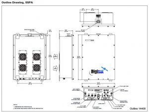
Mechanical Specifications
|
Size HPA Chassis |
width X height X depth |
19.0 X 10.47 X 30.0 483 X 266 X 762 |
inches mm |
||
|
Power Supply Chassis |
width X height X depth |
19.0 X 1.75 X 16.1 483 X 44 X 409 |
inches mm |
||
|
Weight HPA Chassis Power Supply Chassis (1RU) |
180 (82) 29 (13) |
lbs.(kg) lbs.(kg) |
|
||
|
Finish |
powder coat |
Gray |
|
||
Environmental
|
Operating Temperature |
Ambient |
0 to +50 |
°C |
|
Relative Humidity |
Condensing |
95 |
% |
|
Cooling System |
Integrated |
Forced air |
|
7RU SSPA Interface Specifications
|
PORT |
NOTES |
LIMITS |
PIN-OUT |
|||||
|
Monitor & Control (J7) |
Parallel Port Outputs |
Power Supply Fault Auxiliary Fault Mute BUC Fault Temperature Fault Voltage Fault DC Current Fault Low RF Fault |
Form C relay Form C relay Form C relay Form C relay Form C relay Form C relay Form C relay Form C relay |
|||||
|
Monitor & Control (J7) |
Parallel Port Inputs |
Mute Input Local / Remote Fault Clear Standby Select Auxiliary Fault Ground |
Opto Isolator Opto Isolator Opto Isolator Opto Isolator Opto Isolator |
|||||
|
Main Serial Port (J4) |
RS232 / RS485 |
RS232 Out, RS485 TX- |
Pin 2 |
|||||
|
DB9 (F) |
RS232 In, RS485 RX- |
Pin 3 |
|
|||||
|
RS485 RX+ |
Pin 4 |
|
||||||
|
RS485 TX+ |
Pin 1 |
|
||||||
|
Service Request 1 |
Pin 6 |
|
||||||
|
Service Request 2 |
Pin 8 |
|
||||||
|
Service Request Common |
Pin 7 |
|
||||||
|
Termination |
Pin 9 |
|
||||||
|
Ground |
Pin 5 |
|
||||||
|
Auxiliary Serial Port (J5) |
RS232 / RS485 |
RS232 In, RS485 RX- |
Pin 2 |
|||||
|
DB9 (F) |
RS232 Out, RS485 TX- |
Pin 3 |
|
|||||
|
RS232 DTR, RS485 TX+ |
Pin 4 |
|
||||||
|
RS485 RX+ |
Pin 1 |
|
||||||
|
Termination |
Pin 9 |
|
||||||
|
Ground |
Pin 5 |
|
||||||
|
Link Port (J8) |
1:1 Redundant System Control Link |
RS485+ |
Pin 1,4 |
|||||
|
DB9 (F) |
RS485- |
Pin 2,3 |
|
|||||
|
Link Out |
Pin 6,7 |
|
||||||
|
Link In |
Pin 8,9 |
|
||||||
|
Ground |
Pin 5 |
|
||||||
|
Switch Port (J3) |
Redundant Switch Control |
+28 VDC |
Pin 1,4 |
|||||
|
Molex (43810-0002) |
RF Switch 1, pos 1 |
Pin 3 |
|
|||||
|
RF Switch 1, pos 2 |
Pin 2 |
|
||||||
|
RF Switch 2, pos 1 |
Pin 6 |
|
||||||
|
RF Switch 2, pos 2 |
Pin 5 |
|
||||||
|
Program Port (J6) |
Flash Firmware Program Port |
DB25(F) |
- |
|||||
|
Ethernet Port (J9) |
RJ45 |
TX+ |
Pin 1 |
|||||
|
TX- |
Pin 2 |
|
||||||
|
RX- |
Pin 3 |
|
||||||
|
RX+ |
Pin 6 |
|
||||||
|
Ground |
Pins 4,5,7,8 |
|
||||||
|
Connectors |
RF Input, Input & Output Sample RF Output HPAK7XXXR HPAC7XXXR HPAX7XXXR Line Power |
Type N WR75 Waveguide WR137 Waveguide WR112 Waveguide (3) IEC feeds |
Female Grooved (PBR-120) CPR137G flange CPR112G (PDR-84) Plug |
|||||
Video Broadcasting, Teleports, Earth Stations, Uplink Facilities, Satellite News Gathering