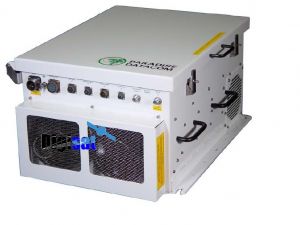
Teledyne Paradise Datacom 7RU X-Band Milsatcom Solid State Power Amplifier

Built-in 1:1 Redundancy Control, Milsatcom compatible, Ideal for government Communications Networks
7RU X-Band Milsatcom Solid State Power Amplifier
The Teledyne Paradise Datacom 7RU Indoor X-Band High Power Rack Mount series of SSPAs represent the industry’s highest power density and most reliable high power amplifier systems.
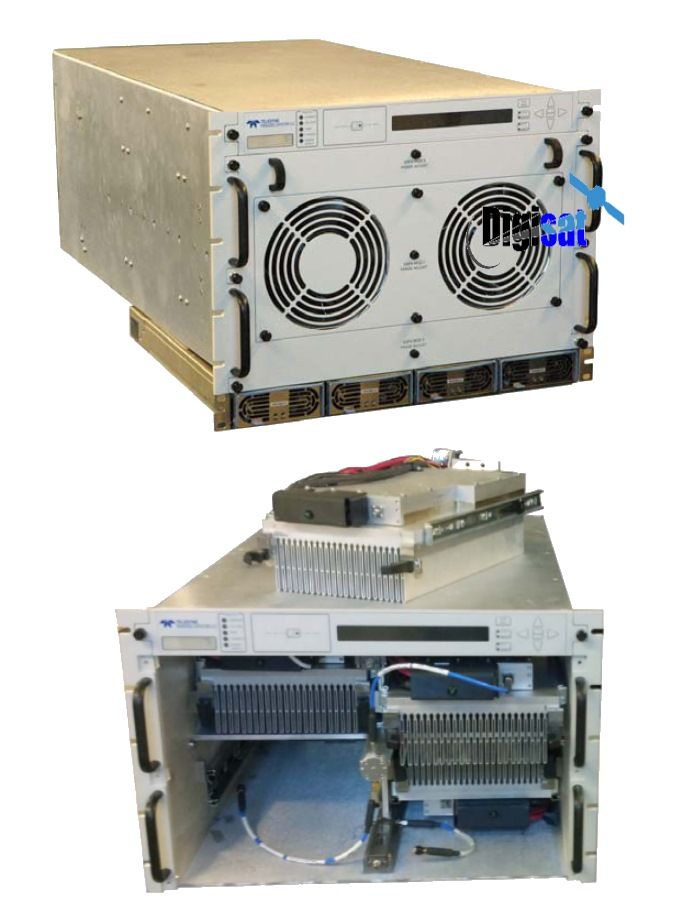
Modular Power Supplies
The High Power Rack Mount SSPA employs a modular design, which allows quick and easy replacement in the event of a catastrophic failure of one of the SSPA components. These modular assemblies include: hot-swap SSPA modules, front and rear fan trays; and a rear panel controller card. These amplifiers are powered via a separate power supply chassis.
Full Redundant Capability
The power supply is configured as a n+1 redundant, hot swappable, power supply comprised of four modules. Only three modules are required to operate the HPA, therefore one module is redundant. In the event of a power supply module failure, the amplifier system will not fail. The module can then be changed without ever taking the HPA out of service.
Paradise 7RU SSPA frequency plans
|
Band |
Frequency Band |
IF Input |
LO Frequency |
RF Output |
Gain Change |
|
C |
Standard C-Band |
950 - 1525 MHz |
4.900 GHz |
5.850 - 6.425 GHz |
0-4 dB |
|
C |
Extended C-Band |
950 - 1825 MHz |
4.900 GHz |
5.850 - 6.725 GHz |
0-4 dB |
|
C |
Palapa Band |
950 - 1250 MHz |
5.475 GHz |
6.425 - 6.725 GHz |
0-4 dB |
|
C |
Insat Band |
950 - 1250 MHz |
5.775 GHz |
6.725 - 7.025 GHz |
0-4 dB |
|
C |
Extended C-Band 2 |
950 - 1675 MHz |
4.800 GHz |
5.750 - 6.475 GHz |
0-4 dB |
|
X |
Standard X-Band |
950 - 1450 MHz |
6.950 GHz |
7.900 - 8.400 GHz |
0-2 dB |
|
Ku |
Standard Ku-Band |
950 - 1450 MHz |
13.050 GHz |
14.00 - 14.50 GHz |
0-2 dB |
|
Ku |
Extended Ku-Band |
950 - 1700 MHz |
12.800 GHz |
13.75 - 14.50 GHz |
0-2 dB |
|
BAND |
PARAMETER |
NOTES |
LIMITS |
UNITS |
||
|
C-BAND |
Frequency Range |
(see options for extended band) |
5.850 to 6.425 |
GHz |
||
|
Output Power @: Saturation/P1dB (Typical/Guaranteed minimum) |
HPAC7800ARXXXXX HPAC7900ARXXXXX HPAC711KARXXXXX |
Psat / P1dB 59.0 / 58.0 (800 / 630) 59.5 / 58.5 (900 / 700) 60.4 / 60.0 (1100 / 1000) |
dBm (W) dBm (W) dBm (W) |
|||
|
Power Requirements Line Voltage Line Frequency Power Factor Line Power |
HPAC7800ARXXXXX HPAC7900ARXXXXX HPAC711KARXXXXX |
180 to 265 47 to 63 .90 4150 4850 6000 |
VAC Hz W W W |
|||
|
X-BAND |
Frequency Range |
7.9 to 8.4 |
GHz |
|
||
|
Output Power @: Saturation/P1dB (Typical/Guaranteed minimum) |
HPAX7700ARXXXXX HPAX710KARXXXXX |
Psat / P1dB 58.5 / 58.1 (700 / 650) 60.0 / 59.5 (1000 / 900) |
dBm (W) dBm (W) |
|||
|
Power Requirements Line Voltage Line Frequency Power Factor Line Power |
HPAX7700ARXXXXX HPAX710KARXXXXX |
180 to 265 47 to 63 .90 5500 6000 |
VAC Hz W W |
|||
|
KU-BAND |
Frequency Range |
(see options for extended band) |
14.0 to 14.5 |
GHz |
||
|
Output Power @: Saturation/P1dB (Typical/Guaranteed minimum) |
HPAK7400ARXXXXX HPAK7500ARXXXXX |
Psat / P1dB 56.0 / 55.0 (400 / 300) 57.0 / 56.0 (500 / 400) |
dBm (W) dBm (W) |
|||
|
Power Requirements Line Voltage Line Frequency Power Factor Line Power |
Power Factor Corrected HPAK7400ARXXXXX HPAK7500ARXXXXX |
180 to 265 47 to 63 .90 4600 5100 |
VAC Hz W W |
|||
SSPA Options
|
Extended C-Band 5.850 to 6.725 GHz 5.750 to 6.670 GHz |
De-rate power by 1.0 dB linearly from 6.425 to 6.725 GHz De-rate power by 1.0 dB linearly from 6.425 to 6.670 GHZ and by 0.5 dB from 5.750 to 5.850 |
HPAC7XXXBRXXXXX HPAC7XXXCRXXXXX |
|
|
Extended Ku-Band 13.75 to 14.5 GHz |
De-rate power by 1.0 dB linearly from 13.75 to 14.0 GHz |
HPAK7XXXBRXXXXX |
|
|
Reflected Power Monitor |
See Configuration Matrix |
|
|
|
RF Input Sample Port (-10 dB) |
See Configuration Matrix |
|
|
General Specifications
|
General Specifications: 7RU RM Series PARAMETER |
NOTES |
LIMITS |
UNITS |
|
|
Gain Gain Flatness Gain Slope Gain Variation vs. Temperature Gain Adjustment |
minimum full band Extended C-Band units per 40 MHz 0 °C to +50 °C 0.1 dB resolution adjustable by either serial or analog voltage input: 0.5 to 2.5 VDC |
75 r 1.0 r 1.5 + 0.3 r 1.0 20 |
dB dB dB dB/40 MHz dB dB |
|
|
Intermodulation Distortion |
3dB back off relative to P1dB |
-25 |
dBc |
|
|
AM/PM Conversion |
(@ rated P1dB) (@P1dB-3dB) |
3.5 0.5 |
°/dB °/dB |
|
|
Spurious Harmonics |
(@ rated P1dB) (@ rated P1dB-3dB) |
-60 -50 |
dBc dBc |
|
|
Input/Output VSWR |
All units except Extended C-Band Extended C-Band units1 |
1.30:1 1.50:1 |
|
|
|
Noise Figure |
at maximum gain |
12 |
dB |
|
|
Group Delay (per 40 MHz segment) |
Linear Parabolic Ripple |
0.01 0.003 1.0 |
ns/MHz ns/MHz2 ns p-p |
|
|
Noise Output |
TX Band (C-, X- or Ku-Band) RX Band (C- or Ku-Band) RX Band (X-Band) |
-75 -150 -100 |
dBW/4 KHz dBW/4 KHz dBW/4 KHz |
|
|
Residual AM Noise |
0 - 10 KHz 10 KHz - 500 KHz 500 KHz - 1 MHz |
-45 -20 (1.25 + log F) -80 |
dBc dBc dBc |
|
|
Phase Noise |
IESS –308/309 - 10 dB |
|
||
Mechanical
|
Size HPA Chassis |
width X height X depth |
19.0 X 10.47 X 30.0 483 X 266 X 762 |
inches mm |
||
|
Power Supply Chassis |
width X height X depth |
19.0 X 1.75 X 16.1 483 X 44 X 409 |
inches mm |
||
|
Weight HPA Chassis Power Supply Chassis (1RU) |
180 (82) 29 (13) |
lbs.(kg) lbs.(kg) |
|
||
|
Finish |
powder coat |
Gray |
|
||
Environmental
|
Operating Temperature |
Ambient |
0 to +50 |
°C |
|
Relative Humidity |
Condensing |
95 |
% |
|
Cooling System |
Integrated |
Forced air |
|
7RU Series SSPA Interface Specifications
|
PORT |
NOTES |
LIMITS |
PIN-OUT |
|||||
|
Monitor & Control (J7) |
Parallel Port Outputs |
Power Supply Fault Auxiliary Fault Mute BUC Fault Temperature Fault Voltage Fault DC Current Fault Low RF Fault |
Form C relay Form C relay Form C relay Form C relay Form C relay Form C relay Form C relay Form C relay |
|||||
|
Monitor & Control (J7) |
Parallel Port Inputs |
Mute Input Local / Remote Fault Clear Standby Select Auxiliary Fault Ground |
Opto Isolator Opto Isolator Opto Isolator Opto Isolator Opto Isolator |
|||||
|
Main Serial Port (J4) |
RS232 / RS485 |
RS232 Out, RS485 TX- |
Pin 2 |
|||||
|
DB9 (F) |
RS232 In, RS485 RX- |
Pin 3 |
|
|||||
|
RS485 RX+ |
Pin 4 |
|
||||||
|
RS485 TX+ |
Pin 1 |
|
||||||
|
Service Request 1 |
Pin 6 |
|
||||||
|
Service Request 2 |
Pin 8 |
|
||||||
|
Service Request Common |
Pin 7 |
|
||||||
|
Termination |
Pin 9 |
|
||||||
|
Ground |
Pin 5 |
|
||||||
|
Auxiliary Serial Port (J5) |
RS232 / RS485 |
RS232 In, RS485 RX- |
Pin 2 |
|||||
|
DB9 (F) |
RS232 Out, RS485 TX- |
Pin 3 |
|
|||||
|
RS232 DTR, RS485 TX+ |
Pin 4 |
|
||||||
|
RS485 RX+ |
Pin 1 |
|
||||||
|
Termination |
Pin 9 |
|
||||||
|
Ground |
Pin 5 |
|
||||||
|
Link Port (J8) |
1:1 Redundant System Control Link |
RS485+ |
Pin 1,4 |
|||||
|
DB9 (F) |
RS485- |
Pin 2,3 |
|
|||||
|
Link Out |
Pin 6,7 |
|
||||||
|
Link In |
Pin 8,9 |
|
||||||
|
Ground |
Pin 5 |
|
||||||
|
Switch Port (J3) |
Redundant Switch Control |
+28 VDC |
Pin 1,4 |
|||||
|
Molex (43810-0002) |
RF Switch 1, pos 1 |
Pin 3 |
|
|||||
|
RF Switch 1, pos 2 |
Pin 2 |
|
||||||
|
RF Switch 2, pos 1 |
Pin 6 |
|
||||||
|
RF Switch 2, pos 2 |
Pin 5 |
|
||||||
|
Program Port (J6) |
Flash Firmware Program Port |
DB25(F) |
- |
|||||
|
Ethernet Port (J9) |
RJ45 |
TX+ |
Pin 1 |
|||||
|
TX- |
Pin 2 |
|
||||||
|
RX- |
Pin 3 |
|
||||||
|
RX+ |
Pin 6 |
|
||||||
|
Ground |
Pins 4,5,7,8 |
|
||||||
|
Connectors |
RF Input, Input & Output Sample RF Output HPAK7XXXR HPAC7XXXR HPAX7XXXR Line Power |
Type N WR75 Waveguide WR137 Waveguide WR112 Waveguide (3) IEC feeds |
Female Grooved (PBR-120) CPR137G flange CPR112G (PDR-84) Plug |
|||||
Military Satellite Communications Systems, Forward Network Nodes, Blueforce Tracking Systems, Government Networks