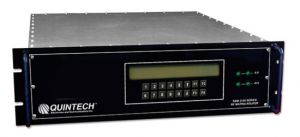
Quintech Electronics RLC48 1750A Redundant Active L-Band Combiner


48 Ipnuts, Operates over the 950-1750 MHz frequency range

RLC48 1750A Redundant Active L-Band Combiner
This product has reached end of life and is no longer available. Please contact Digisat for a suitable replacement.
Quintech RLC-1750A Redundant Active L-Band RF Combiner is a 48-Way Active Combiner that's Based on Quintech’s RPS series redundant power supplies and the LS2150 series L-band power combiners, the RLC48 1750A provides an active 48 way redundant power combiner operating over the 950-1750 MHz frequency range.
Features
Hot-swappable redundant power supply modules
Hot-swappable redundant combiner modules
9 dB of gain in 1dB steps via front panel mounted rotary switches
Current sensing for combiner failure
Redundant backup amplifier replaces failed amplifier in less than 1 μsec
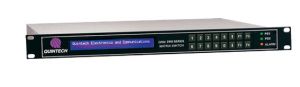
Front panel mounted LED indicators for power supply and combiner status
Front panel mounted momentary switch for manual switching of redundant combiners
RS-422 interface for remote switching of combiner modules
50 Ω BNC termination boards for unused ports (supplied as required)
Dual AC power supply modules
Front Panel LEDs |
|||||||
|
Front panel mounted LED indicators have been included to indicate power supply and combiner status. Their meanings |
|||||||
|
are as follows: |
|||||||
DC Power Supply Modules |
|||||||
|
Green LED on |
– normal operation |
||||||
|
Green LED off |
– power supply failure |
||||||
Controller Module |
|||||||
|
AC1 / AC2 |
|||||||
|
LED green |
– normal operation |
||||||
|
LED off – AC power failure |
|||||||
|
DC1 / DC2 |
|||||||
|
LED green |
– DC power supply operating normally |
||||||
|
LED red |
– DC power supply failure |
||||||
|
NOTE: In those instances when the green LED goes off on a DC power supply module, its corresponding LED on the |
|||||||
|
controller module will change to red. |
|||||||
Combiner Modules |
|||||||
|
Green LED on (ACTIVE) |
– combiner module is currently online and is operating normally |
||||||
|
Yellow LED on (STANDBY) |
– combiner module is operating normally, but is currently offline and in standby mode |
||||||
|
Red LED on (FAILURE) |
– combiner module is offline and is experiencing a failure |
||||||
|
NOTES: |
For each redundant combiner module pair, only one combiner module can be active at a time; thus, when the |
||||||
|
|
ACTIVE (green) LED is lit on one combiner module, the STANDBY (yellow) LED will be lit on its redundant |
||||||
|
|
combiner module and vice versa. |
||||||
|
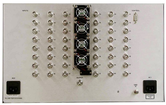
Ports |
48 input / 1 output |
|
Operating Frequency Range |
950 -1750 MHz |
|
Impedance: |
50 Ω |
|
P1dB (Input): |
-4 dBm (each input), different frequency or carrier per input |
|
Gain (Variable): |
0 db to 9 dB in 1dB steps |
|
Frequency Response: |
± 2.5 dB over the operating frequency range |
|
|
± 0.5 dB over any 40 MHz |
|
|
± 0.75 over any 72 MHz |
|
Isolation: |
18 dB min. |
|
Return Loss: |
15 dB min., 18 dB typical |
|
Noise Figure: |
≤ 16 dB |
|
RF Connectors: |
BNC, 50 Ω (female) |
|
Power Requirements: |
100-240 V~, 50/60 Hz |
|
Power Consumption: |
145 W |
|
Redundant Amplifier Switching Speed: |
<1 μsec |
|
Phase Differential: |
5 degree differential |
|
Nominal Input Level: |
-15 dBm |
|
Operating Temperature Range: |
0-50° C |
L-Band signal distribution, cable headends, IPTV