Quintech Electronics QRM 2500 16x16 RF Matrix Routing System QRM250016x16CFFA600


Frequency range covers 50 MHz to 2150 MHz, Manual and automatic AGC modes with a range of -15dB to +16 dB in 0.5 dB steps

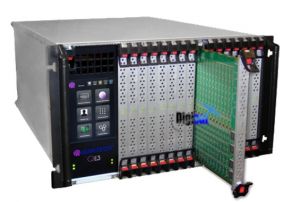
QRM 2500 16x16 RF Matrix Routing System
This product has reached end of life and is no longer available. Please contact us for a replacement solution.
The highly versatile Quintech Electronics QRM 2500 IF and L-band routing matrix features a 16x16 RF matrix routing in a compact 1 RU enclosure. The QRM250016x16CFFA600 series also features Quintech’s latest Q-ROUTE and Q-SENSE technology, which provides maximum reliability with internal and external signal path redundancy and auto re-route capabilities. The QRM’s operating frequency range covers 50 MHz to 2150 MHz and also offers manual and automatic AGC modes with a range of -15dB to +16 dB in 0.5 dB steps with optional LNB Power and individual port control to support all modulation formats. The front panel LED’s allow monitoring of power supply and alarm status information.

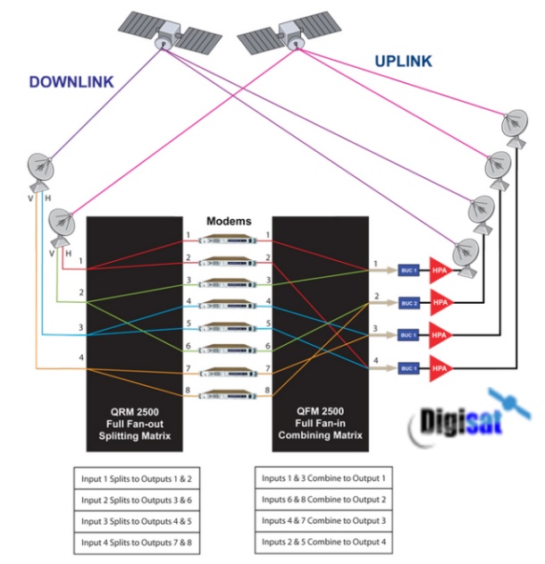
Full Fan In and Out Matrix Switch System shown here with the Quintech QRM 2500 Combiner
Benefits
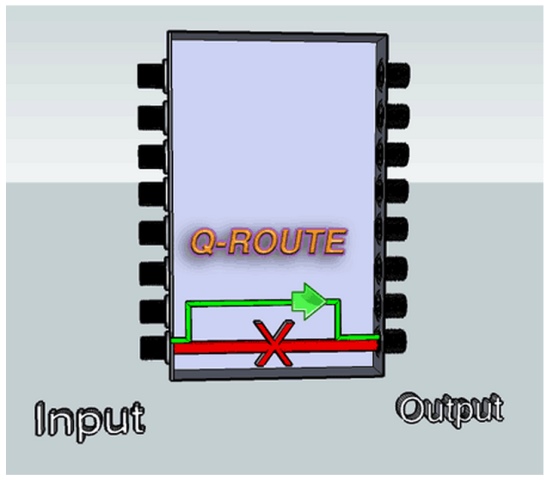
Q-ROUTE Provides Internal Signal Path Redundancy by Automatically Re-routing Around a Failed Signal Path
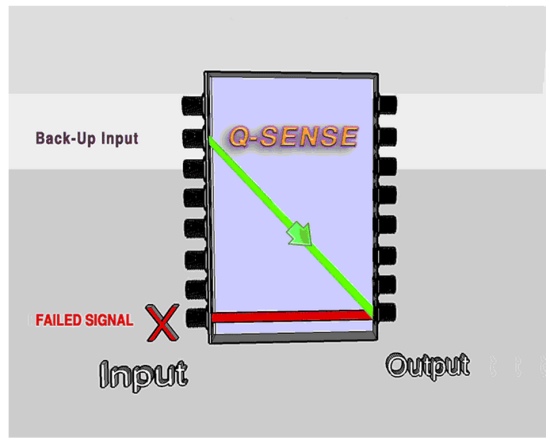
Q-SENSE Provides External Signal Path Redundancy by Automatic Switching of Back-up Input Signals
Quintech QRM 2500 Features
![]() Manual and Automatic AGC Modes with a Range of -15 dB to +16 dB in 0.5 Steps
Manual and Automatic AGC Modes with a Range of -15 dB to +16 dB in 0.5 Steps
![]() Front Panel LED's Allow Monitoring of Power Supply & Alarm Status
Front Panel LED's Allow Monitoring of Power Supply & Alarm Status
![]() Modular design allows for easy system installations and expansion
Modular design allows for easy system installations and expansion
![]() Remotely controlled via web browser interface
Remotely controlled via web browser interface
![]() Solid state switches provide seamless (nanoseconds) switching speeds
Solid state switches provide seamless (nanoseconds) switching speeds
![]() Maximize use of existing equipment with automated switching and scheduling' no need for dedicated equipment
Maximize use of existing equipment with automated switching and scheduling' no need for dedicated equipment
![]() The rear panel design facilitates structured cable routing, eliminating confusing tangles of cables
The rear panel design facilitates structured cable routing, eliminating confusing tangles of cables
|
16x16 Router |
L-Band |
IF |
|
Operating Frequency: |
(950-2150 MHz) |
(50-200 MHz) |
|
Frequency Response: |
+/- 1.5 +/- 0.4 dB Over any 36 MHz channel |
+/- 2 +/- 0.6 dB Over any 36 MHz channel |
|
Isolation |
|
|
|
(input to input): |
65dB |
65 dB |
|
(output to output): |
60 dB |
60 dB |
|
(input to output): |
50 dB Typ. |
55 dB Typ. |
|
RF Input Power |
-10 dB to -70 dB |
-10 dB to -70 dB |
|
Gain Range (manual mode) |
-15 dBm to +16 dB in 0.5 dB steps |
-15 dBm to +16 dB in 0.5 dB steps |
|
Impedance |
50 Ω or 75 Ω |
50 Ω or 75 Ω |
|
Output AGC level |
-10 dBm to -50 dBm |
-10 dBm to -50 dBm |
|
Max. RF Output Power: |
-10 dBm |
-10 dBm |
|
Input P1dB |
+2 dBm |
-3 dBm |
|
OIP3 |
+10 dBm |
+8 dBm |
|
Input Return Loss: |
14 dB |
14 dB |
|
Output Return Loss: |
14 dB |
14 dB |
|
Noise Figure: |
<18 dB @ 0dB <9.5 dB @ 16 dB |
<18 dB @ 0dB <9.5 dB @ 16 dB |
|
Configurations: |
8x8, 8x16, 16x8, 16x16 |
|
|
RF Connectors: |
BNC (50 or 75 Ω), type "F" , SMA Connectors |
|
|
AC Input Power: |
Auto ranging 100-240 VAC, 50/60 Hz |
|
|
Local Control: |
Front panel keypad with LCD display |
|
|
PC Remote Control: |
RS-232. RS 485, SNMP, Telnet or TCP/IP via customer supplied PC2 |
|
|
Software: |
Basic PC compatible operating software and command protocol included |
|
|
Mechanical: |
16x16 in 1 RU 1.75" H x 19" W x 18.5" D |
|
Content Delivery via Satellite, RF Matrix Switching Applications