Foxcom Sat-Light Ku-Band Tx/RX Optical IFL Link System


Ku-Band Transmit and Receive System, 10.7 to 12.75 and 12.75 to 14.5 GHz
Foxcom Sat-Light Ku-Band Tx/RX Optical IFL Link System
Foxcom's Sat-Light KU-Band fiberoptic interfacility links transmit and receive downlink signals in the 10.7-12.75 and 12.75 to 14.5
GHz range between antennas and control rooms or NOCs. Foxcom's IFLs offer a high performance alternative to conventional
coaxial-cabled systems, reducing the need for waveguide and minimizing signal attenuation.
The Sat-Light IFLs function as a transparent link, transmitting all satellite modulation formats carrying an entire polarization on each
link. System limitations in using coaxial cable are overcome by the simplicity and performance of fiberoptic connections to provide
the highest levels in signal quality. Foxcom achieves this by using state of the art lasers to provide high efficiency, low noise analog
links.
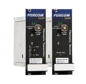
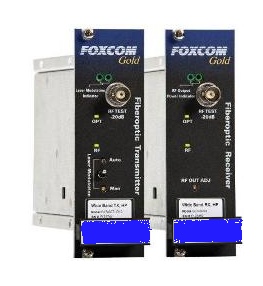
A typical KU-Band link consists of an optical transmitter that receives the RF signal, transmits it over a single mode fiber to an
optical receiver and reconverts the optical signal to RF. Foxcom's advanced fiberoptic technology reduces the attenuation, slope,
phase shift, and group delay maintaining extremely low levels over distances of up to 15 kilometers.
The KU-Band's link cost effective high performance lasers produce negligible chirp and optical distortion, which is critical for long
distance links. The EAM monolithic design, versus connectorized component electro-optics, assures high performance along with
excellent reliability. The links are provided with test ports, status and fault LEDs, and gain controls.
GL952KU KU-Band Optical Uplink
Features & Benefits
Optimized for Professional Satellite Applications
15Km Transmission Distance
Transmitter and Receiver Gain Control
Front Panel Test Port
Powerful Monitoring Features
Compatible with all 1st Generation SatLight Products
GL952KD KU-Band Optical Downlink
Features & Benefits
10.7-12.75 GHz
Group Delay Variation- linear 10.7-12.75 GHz- 0.4
Maximum RF Input without damage- +10 dBm
TX/RX Input/Output VSWR @50 Ohm- 1.4:1 dB
Ordering Information
GL952KU-T – Gold KU-Band Uplink Transmitter
GL952KU-R – Gold KU-Band Uplink Receiver
Extremely Low Loss:
Satellite Markets- Fiber Optic IFL System Overview with Digisat's CEO
Whether your requirements are for a single pre-engineered fiber optic IFL system or a fully engineered solution, Digisat can deliver a total turnkey solution including installation, integration and testing.
Uplink
|
RF Specifications |
Units |
Typical |
Minimum |
Maximum |
|
Frequency Range |
GHz |
13.75-14.5 |
|
|
|
Link Gain |
dB |
Adjustable |
-10 |
+10 |
|
Amplitude Response @ Unity Gain 13.75-14.5GHz and 36 MHz |
dB |
±1 ±0.2 |
|
|
|
Gain Stability @ Constant Temp |
dB/24hr |
|
|
±0.15 |
|
SFDR1 |
dB/Hz2/3 |
102 |
100 |
|
|
CNR [36 MHz @ 2.5GHz]2 |
dB |
55 |
50 |
|
|
Noise Figure (NF)2 |
dB |
|
|
22 |
|
Output IP3 (OIP3)1 |
dB |
|
+15 |
|
|
Third Order Inter-Modulation [IMD]3 |
dBc |
|
-55 |
-50 |
|
Group Delay Variation ─ linear 14 to 14.5 GHz |
ns |
0.4 |
|
|
|
Input Signal Range ─ Total Power |
dBm |
|
-25 |
-5 |
|
RF Output Signal Range ─ Total Power |
dBm |
|
-25 |
-5 |
|
Maximum Input without Damage |
dBm |
|
+5 |
|
|
Input/Output Impedance |
Ohm |
50 |
|
|
|
TX/RX Input/Output VSWR @50 Ohm |
dB |
|
1.4:1 |
|
|
RF Connector Type Input/Output
Test Port |
|
SMA
SMA |
|
|
|
Test Port [front panel sample port] |
dB |
-20 |
-22 |
-18 |
Optical Specifications |
Units |
Typical |
Minimum |
Maximum |
|
Optical Power Output |
dBm |
-1 |
-3 |
2 |
|
Optical Budget / Distance 3 dB optical budget |
dB/Km |
15Km@1550nm |
|
|
|
Optical Connector Types |
|
FC/APC |
|
|
|
Optical Wavelength |
nm |
1550/CWDM |
|
|
|
Electrical Specification |
|
|
|
|
|
Supply Voltage |
Vdc |
13 |
12.7 |
18 |
|
Supply Current [TX]4 |
Amps |
0.8 |
|
|
|
Supply Current (RX) |
Amps |
0.5 |
|
|
Downlink
RF Specifications |
Units |
Typical |
Minimum |
Maximum |
|
Frequency Range |
GHz |
10.7-12.75 |
|
|
|
Link Gain |
dB |
Adjustable |
-10 |
+10 |
|
Amplitude Response @ Unity Gain 10.7-12.75GHz and 48 MHz |
dB |
±1 ±0.2 |
|
|
|
Gain Stability @ Constant Temp |
dB/24hr |
|
|
±0.15 |
|
SFDR |
dB/Hz |
|
100 |
|
|
CNR |
dBc |
|
50 |
|
|
Noise Figure (NF) |
dB |
|
|
22 |
|
Output IP3 (OIP3) |
dB |
|
+20 |
|
|
Third Order Inter-Modulation [IMD]¹ |
dBc |
Adjustable |
-55 |
-50 |
|
Group Delay Variation- linear 10.7-12.75 GHz |
ns |
0.4 |
|
|
|
Input Signal Range ─ Total Power |
dBm |
|
-5 |
-25 |
|
RF Output Signal Range ─ Total Power |
dBm |
|
-5 |
-25 |
|
Maximum RF Input without damage |
dBm |
|
+10 |
|
|
Input/Output Impedance |
ohm |
50 |
|
|
|
TX/RX Input/Output VSWR @50 Ohm |
dB |
|
1.4:1 |
|
|
RF Connector Type Input/Output
Test Port |
|
SMA
SMA |
|
|
|
Test Port [front panel sample port] |
dB |
-20 |
-19 |
-21 |
Optical Specifications |
Units |
Typical |
Minimum |
Maximum |
|
Optical Power Output |
dBm |
|
-2 |
0 |
|
Optical Budget / Distance 3 dB optical budget |
dB/Km |
15Km@1550nm |
|
|
|
Optical Connector Types |
|
FC/APC |
|
|
|
Optical Wavelength |
nm |
1550/CWDM |
|
|
|
Optical Return Loss |
dB |
-60 |
|
|
|
Electrical Specification |
|
|
|
|
|
Supply Voltage |
Vdc |
13 |
12.7 |
18 |
|
Supply Current [TX] |
Amps |
0.8 |
|
|
|
Supply Current (RX) |
Amps |
0.5 |
|
|
Video Uplinks, News gathering, Satellite Teleports, Video Content Delivery