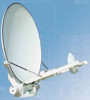
CPI SAT SM-LT 2.4M Mobile Troposcatter Antenna


2.4M, vehicular mount Troposcatter antenna system

SM-LT 2.4M Mobile Troposcatter Antenna
This product has reached end of life and is no longer available. Please contact us for information on a comparable replacement.
The CPI SAT (formerly GD Satcom Technologies & Prodelin) 2.4m SM-LT antenna, configured for troposcatter operation, utilizes either a “conventional” C-band (4.4 to 5.0 GHz) feed or a proprietary dual-beam Ku-band feed (14.9 to 15.4 GHz) to provide high-quality, over-the-horizon communications. In C-band applications, space diversity is normally achieved using dual antennas in each terminal. For Ku-band applications, a unique, patent-pending, dual-beam feed is incorporated to provide two closely-spaced beams in elevation to achieve angle diversity in the troposcatter link.
Rugged Construction
Engineered to stringent standards for multiple applications, the 2.4m SM-LT delivers performance suitable for multi-band satcom and troposcatter operation. Various modes and/or frequency bands of operation are readily accommodated via interchangeable feed packages, making the antenna truly field-configurable. In any operational mode or frequency band, antenna performance is outstanding, with high gain, low sidelobes and high crosspol and port-to-port isolation values. The use of carbon fiber technology and precisionmachined aluminum components provides the ultimate in transportability, wind performance and longevity in tactical environments.
Precision Control
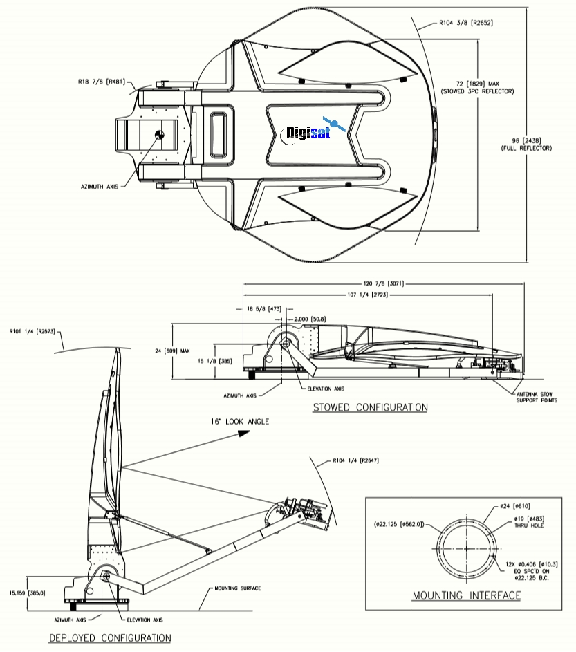
With an integral azimuth over elevation cable drive and lower azimuth bearing, the antenna system is readily fitted to HMMWVs, trailers or transportable pallets. The 2.4m SM-LT is fully compatible with the industry-standard CPI SAT Model 123T Antenna Control System, which provides position control and tracking, as well as auto-deploy and auto-stow functionality for both troposcatter and satcom modes of operation.
Options
- Complete tropo terminals available, including amplifiers, frequency converters, modems, antenna control systems and monitor and control systems
- Reflector configurations (single or three-piece segmented)
- Finishes (green, tan or per customer spec)
- Integration (various TWT/amplifier mounting arrangements)
- Anti-icing
- Satcom capable (L, C, X, Ku, DBS, Ka, low-PIM)
Frequency (GHz) 4.400 - 5.000 4.400 - 5.000 14.900 - 15.400 14.900 - 15.400
Antenna Gain at Midband, dBi 38.30 38.30 49.70 49.70
Antenna Noise Temperature 81 K (1° elevation) 121 K (1° elevation)
72 K (2° elevation) 101 K (2° elevation)
40 K (10° elevation) 58 K (10° elevation)
36 K (20° elevation) 50 K (20° elevation)
Typical G/T
at 20° Elevation, Clear Horizon, 4.400 GHz
35° K LNA 18.1 dB/K
50° K LNA 17.3 dB/K
at 1° Elevation, Clear Horizon, 15.150 GHz
70° K LNA 26.7 dB/K
90° K LNA 26.2 dB/K
Pattern Beamwidth (in degrees at midband)
-3 dB Beamwidth 2.08 2.08 0.54 0.54
-15 dB Beamwidth 4.37 4.37 1.13 1.13
Sidelobe Performance
First Sidelobe Across the Band -20.0 ± 2 dB -20.0 ± 2 dB -20.0 ± 2 dB -20.0 ± 2 dB
For Angle A from 14° to 22° -26 dB -26 dB -26 dB -26 dB
For Angles Greater Than 22° -30 dB -30 dB -30 dB -30 dB
Cross Polarization Isolation
On Axis 30.0 dB 30.0 dB 30.0 dB 30.0 dB
Within 1.0 dB Beamwidth 30.0 dB 30.0 dB 30.0 dB 30.0 dB
VSWR 1.30:1 1.30:1 1.30:1 1.30:1
Port-to-Port Isolation
Rx/Tx (Rx frequency) 0 dB -30 dB 0 dB -30 dB
Tx/Rx (Tx frequency) -30 dB 0 dB -30 dB 0 dB
Feed Insertion Loss 0.15 dB 0.15 dB 0.15 dB 0.15 dB
Waveguide Interface Flange CPR-187G CPR-187G WR-62 WR-62
Total Power Handling Capability 2 kW CW 1 kW CW
RF Specification 975-3524 975-3358
C & Ku-Band Troposcatter applications