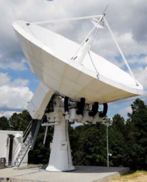
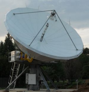
CPI SAT 13.2M Ka-Band Broadband Gateway Antenna System


Precision Ka-band rated surface reflector with counterweights, Transmit signal block downconverters to allow spectrum monitoring at L-band in the control building.
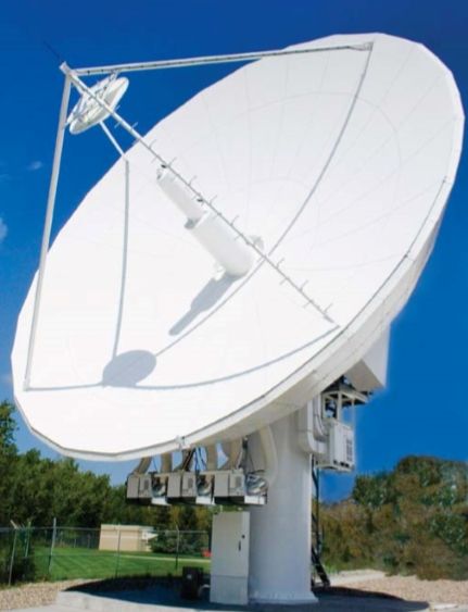
13.2 Meter Ka-Band Antenna
The CPI SAT (formerly GD Satcom Technologies & Prodelin) 13.2M Ka-Band Satellite Earth Station antenna is ideal for IOT, TT&C, DTH, and High Power Uplink applications. Large diameter Ka-band antennas require unique design criteria which GD Satcom has successfully demonstrated with 13.2 meter system. Items such as reflector surface accuracy, antenna/ feed design, structural antenna stiffness and integrity, thermal effects, anti-icing, HPA phase combining, monopulse tracking, installation and alignments and hub integration all require special engineering expertise at Ka-band. Our proven expertise in the above areas and has earned the position as a preferred antenna system provider and integrator to a number of major satellite broadcasting companies by providing in excess of fifty systems of this type over the past five years alone.
|
Reflector |
13.2 meter, counterweight |
|
|
Optics Configuration |
Cassegrain |
|
|
Frequency Transmit Receive |
Standard Band 28.35-30.00 GHz 18.30-20.20 GHz |
Custom Band 27.50-31.00 GHz 17.70-21.20 GHz |
|
Antenna Gain (Standard Band) Transmit @ Feed Tx Port Input Receive @ LNA Input |
69.1+20Log(F/30) dBi66.3+20Log(F/20.2) dBi |
|
|
G/T (min) @ 30° Elevation and 120K LNA (Standard Band) |
42.2 + 20 Log (F/20.2) dBi/K (includes Feed to LNA losses for 1:2 LNA Redundancy) |
|
|
Polarization (Transmit and Receive) |
Dual Circular |
|
|
3 dB Beamwidth Transmit Receive |
0.06° 0.09° |
|
|
Axial Ratio @ 1dB BW (X-POL Isolation in dB) |
0.5 dB (30.7 dB) |
|
|
Port to Port Isolation Transmit to Receive Receive to Transmit Transmit to Transmit Receive to Recieve |
85 dB 85 dB 20 dB 20 dB |
|
|
VSWR |
1.35:1 Max |
|
|
Sidelobe Performance (Tx/Rx) |
ITU-RS.580-5 FCC CFR-47 & 25.209 |
|
|
Power Handling |
1 kW CW Per Port, 2 kW Total |
|
|
Feed Waveguide Flange |
Rx (WR-42), Tx (WR-34) |
|
|
Pressurization Operational Maximum |
0.5 psi2.0 psi |
|
|
Elevation Travel |
0 to 90° Continuous |
|
|
Azimuth Travel |
±100° Continuous |
|
|
Axis Velocity |
0.5°/s |
|
|
Axis Acceleration |
0.2°/s2 |
|
|
Azimuth Drive Configuration |
Gear and Pinion AZ dual Motor Drives |
|
|
Elevation Drive Configuration |
Jackscrew – Single Motor Drive |
|
|
Motor Type for Azimuth and Elevation |
Servo Motor |
|
|
Antenna Two-Axis Pointing Performance (over 10 degree of axis travel) |
0.0083° RMS, No Wind0.0136° RMS Winds 30 mph gusting to 45 mph |
|
|
Tracking Performance for Optrack (C/No: 45 dB-Hz) |
0.0041° RMS, No Wind0.0070° RMS Winds 45 mph gusting to 60 mph |
|
|
Tracking Performance for Monopulse (C/No: 45 dB-Hz) |
0.0028° RMS, No Wind0.0031° RMS Winds 45 mph gusting to 60 mph |
|
|
Tracking Modes |
Program TrackOptrack /Step Track Monopulse |
|
|
Anti-Icing |
Feed Blower Heated Subreflector Optional Primary Reflector – Gas or Electric (as required) |
|
Ka-Band RF Transmission Services, Broadband DTH Internet