Terrasat VSAT LNB 1:1 Receive Redundancy System


Freq Range 950 to 2000 MHz,,Insertion Loss,4 dB max, Flatness 1 dB p-p max, Input/Output VSWR 2:1 max, Connectors N-type (F), F-type optional

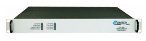
LNB 1:1 Receive Redundancy System
The Terrasat receive 1:1 redundancy system completes the full 1:1 protection configuration for the IBUC Intelligent Block Upconverter system. A completely outdoor-mounted system, the RX interface box is housed in a weatherproof enclosure close to the LNB assembly in order to minimize cable lengths.
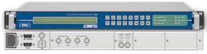
The interface box provides LNB monitoring, waveguide switching and user interfaces. Several operating parameters are monitored including 10MHz reference signal, LNB supply voltage, LNB current consumption, and input compo-site power level. The user can set high and low threshold values for monitored parameters and alarms are configurable to enable selection of specific alarms and thresholds that will trigger a switchover.
Monitoring and control is available using a convenient TCP/IP interface supported by embedded webpages. The TCP/IP interface enables users to monitor the system remotely from a PC and /or via a LAN. M&C is also available via RS232/485 and separate handheld terminal. Seven LED’s provide visual indication of status.
The RX 1:1 system is designed to receive DC power from the redundant power supplies used in Terrasat TX 1:1 systems. Options are available for direct AC or -48VDC input to the RX system. Mounting the interface box is straightforward using the same universal mounting bracket as other Terrasat products. The LNB assembly can be either plate mounted or attached directly to the antenna feed assembly.
All components are designed for outdoor mounting in weather-proof enclosures.
DC or AC power options
Multiple choices for local and remote M&C including:![]() TCP/IP
TCP/IP![]() SNMP
SNMP![]() RS232/485
RS232/485![]() Hand Held Terminal
Hand Held Terminal![]() Multi-function LED’s
Multi-function LED’s
Several operating parameters are monitored including:![]() LNB current
LNB current![]() Supply voltage
Supply voltage![]() 10MHz reference level
10MHz reference level![]() Composite power level
Composite power level
Alarm thresholds and switching criteria are configurable for maximum flexibility. Embedded web pages pro-vide management for small networks using any web browser. Manual override switch is fitted for test and emergency manual operation.
|
RX 1:1 Interface Module |
|||
|
L-band |
|
|
|
|
Frequency Range |
950 to 2000 MHz (950 to 2750 MHz optional) |
||
|
Insertion Loss |
4 dB max |
|
|
|
Flatness |
|
|
|
|
Any 36 MHz band |
1 dB p-p max |
|
|
|
Full Band |
2 dB p-p max |
|
|
|
Input/Output VSWR |
2:1 max |
|
|
|
Connectors |
N-type (F), F-type optional |
||
|
10 MHz Reference (from external demod) |
|||
|
Insertion loss (includes split) |
6 dB max |
||
|
|
|
||
|
Sensors |
|
||
|
A and B L-band input composite level |
|||
|
10 MHz reference level detector (demod input) |
|||
|
A and B LNB supply voltage detector |
|||
|
A and B LNB supply current detector |
|||
|
LED Indicators |
|
|
|
|
Power |
Ethernet Activity |
||
|
A and B Alarm |
Normal / Emergency |
||
|
A and B Online |
|
|
|
|
|
|
||
|
WG Switch Control |
|
|
|
|
Manual/Auto Controller pulses WG switch |
|||
|
Emergency Toggle triggers pulse for WG switch |
|||
|
|
|
|
|
|
WG Switches |
C-band |
X-band |
|
|
Frequency |
3.3-4.9 GHz |
7.05-10.00 GHz |
|
|
VSWR |
1.05:1 |
1.1:1 |
|
|
Insertion Loss |
0.02 dB max |
0.05 dB max |
|
|
Isolation |
80 dB min |
80 dB min |
|
|
Switching time |
200 ms max |
100 ms max |
|
|
Waveguide |
WR 229 |
WR112 |
|
|
|
Ku-band |
Ka-band |
|
|
Frequency |
10-15 GHz |
18-26.5 GHz |
|
|
VSWR |
1.1:1 |
1.1:1 |
|
|
Insertion Loss |
0.05 dB max |
0.15 dB max |
|
|
Isolation |
75 dB min |
60 dB min |
|
|
Switching time |
80 ms max |
80 ms max |
|
|
Waveguide |
WR75 |
WR42 |
|
All VSAT and earth station applications where receive redundancy is required