Quintech Electronics Xtreme 32 L-Band (Fan-Out) RF Matrix Switch


Frequency range covers 850 MHz to 2500 MHz, 8x24, 16x16 L-band switching configurations available

Xtreme 32 L-Band (Fan-Out) RF Matrix
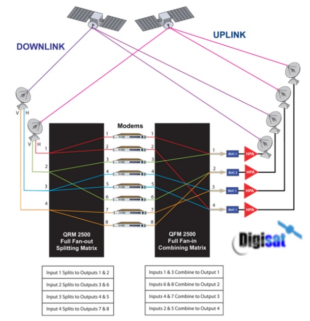
The Quintech Xtreme 32 is a full fan-out (distributive), non-blocking switch where an input can be routed to any or all outputs and features an industry exclusive flexible architecture that supports both symmetric and asymmetric configurations of 32 combined inputs and outputs in a single chassis. Asymmetric configurations such as 4x28, 8x24, and more can be implemented as well as the standard 16x16 configuration. Optional 13/18 V, 22 kHz tone LNB power is available on all input ports. It is designed for maximum reliability with redundant and hot-swappable power supplies. The Quintech Xtreme 32 next generation L-band matrix switch features 32 ports in a compact 1 RU chassis.
Features
-
32 Port Fan-Out L-Band RF Matrix Switch
-
Compact design with a variety of configurations adding to 32 ports in 1 RU
-
Easisly hot-swappable power supplies
-
Independent input and output gain control
-
Remotely controlled via web browser GUI interface, SNMP, Telnet or TCP/IP via customer supplied PC

Typical full fan in and out matrix switch system shown here
Benefits
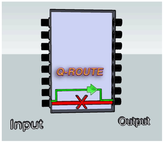
Q-ROUTE Provides Internal Signal Path Redundancy by Automatically Re-routing Around a Failed Signal Path
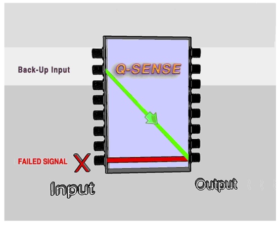
Q-SENSE Provides External Signal Path Redundancy by Automatic Switching of Back-up Input Signals
Operating Frequency: 850-2500 MHz
Configurations: 8x24, 16x16
Input Gain Range: -19 to 12 dB in 0.5 dB steps
Output Gain Range: -14 to 17 dB in 0.5dB steps
Impedance: 75 Ω or 50 Ω Input P1dB: 0 dBm min
OIP3: 10 dBm min (950-2150 MHz)
Frequency Response: +/- 1.5 dB (950-2150 MHz) +/- 0.5 dB over any 36 MHz channel
Isolation (input-to-input): 60 dB
Isolation (output-to-output): 60 dB
Isolation (input-to-output): 55 dB
Input Return Loss: 14 dB
Output Return Loss: 14 dB
Noise Figure: 13 dB @ 0 dB Gain
RF Connectors: F-Type, BNC 75 Ω or 50 Ω, SMA, or Mixed
LNB Power: Each Port 0/13/18 V, 22 kHz Tone
400 mA nominal (550mA peak in-rush)
Short Circuit Protection with Automatic Reset
Status: Under Current (<50mA), Short and Normal
Power Requirements: 100-240 VAC
Autoranging, 50/60 Hz
Power Consumption: 90W typical, 200W max with LNB optional
Local Control: Front panel 2.2” display and rotary switch joystick
Remote Control: SNMP, TELNET, TCP/IP, Web Browser Interface Via Ethernet Remote Panel
Content Delivery via Satellite, RF Matrix Switching Applications, supports both symmetric and asymmetric configurations of 32 combined inputs and outputs in a single chassis.