Quad-Band (C, X, Ku, Ka-Band) Satellite Simulation System


Quad Band - X, C, Ku, Ka-Band, Phase Noise 10 dB (typical) better than IESS 308/309

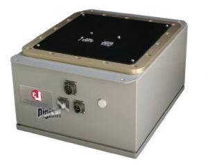
Quad-Band Simulator
Digisat Quad-Band Satellite Simulator System- With the Wideband Global SATCOM (WGS) becoming operational, Digisat has expanded its Satellite Simulator product line beyond Tri-band, now including both Quad-band and Ka-band capabilities. Designed for use as a training test-bed, Digisat Satellite simulators can be used by operations personnel to setup and operate satellite earth terminals in the field under realistic operating conditions without the need for an actual satellite.
Signal Acquiring
Use of Digisat simulators in lieu of a satellite permits signal acquisition by the earth terminal, antenna pointing, uplink power adjustment, signal reception, link closure and communications systems adjustment to establish acceptable bit error rates with very low satellite terminal transmit power.
Key Features
- Simulates C-Band, Ku-Band, Ka-Band and X-Band satellites
- Permits earth station set-up without actual satellite available
- Ruggedized/ weatherproof enclosures for outdoor deployment
- Typical operation range is 50-1000 ft (actual range is determined by antenna size and power
- Low-phase noise for digital data
- Wireless remote control (availablewith Quad-Band Simulator)
- Lightweight
- Easy to operate
QUAD-BAND
INPUT CONTROL AND POWER
AC Power 115 to 230 VAC @ 5 watts nominal
DC Power 12 to 24 Volts DC
RF INPUT SIGNALS
C-Band 5.85 to 6.425 GHz @ nominal -15 dBm
X-Band 7.9 to 8.4 GHz @ nominal -15 dBm
Ku-Band 14.0 to 14.5 GHz @ nominal -15 dBm
Ka-Band 30.0 to 31.0 GHz @ nominal -15 dBm
Input levels are dependent on dish size, distance to simulator, and transmitter power
TRANSFER CHARACTERISTICS – ALL BANDS
Phase Noise 10 dB (typical) better than IES 308/309
Midband Gain 30 dB loss + attenuation setting
(measured @ input/output antenna interfaces)
Gain Adjustment 35 dB continuously variable
Gain Ripple Full Band +1.5 dB max
Gain Ripple per 80 MHz +0.75 dB max
Phase Linearity per 5 MHz + 10 deg max
Frequency Translation Accuracy +5kHz nominal, +/-10kHz for Ka-Band
In-band Signal Related Spurious -50 dBc nominal
LO Leakage -90 dBm max
Image Rejection >50 dB
VSWR In and Out 2.0:1
Input and Output Antennas With nominal gains of 6 dB
1 dB Compression Point 0 dBm at 0 dB attenuation
Group Delay +/- 5 ns/40 MHz
PHYSICAL SPECIFICATIONS
Mechanical Dimensions 6” H x 14” D x 12” W Weight <35 lbs
Front Panel Controls 30 dB attenuation (continuous) per band
Front Panel Indicators Lock alarms
Remote Switch Control Band select (50 ft cable)
Simulates C-Band, X-Band, Ku-Band and Ka-Band satellites, Permits earth station and VSAT antenna testing without actual satellite time available, weatherproof enclosures for outdoor deployment