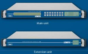
Newtec Azimuth AZ290 1+1 RF Demodulator Redundancy Switching System


1:1 redundancy for Azimuth Series RF Demodulators
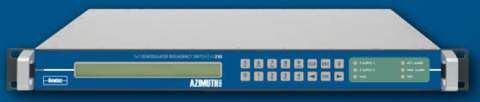
AZ290 Demod Redundant Switch System
This product has reached end of life and has been replaced by the Newtec USS0202.
The Newtec AZ290 1+1 Demodulator Redundancy Switch provides a versatile 1 + 1 protection scheme for satellite demodulators. The AZ290 is easy to operate and switches simultaneously the input IF/L-band signals and output data signals.
Auto Switching
The switching between the main demodulator and the redundant demodulator can be done automatically through alarm contacts, manually through the front panel or the dedicated web interface, or remotely via a monitoring and control system.
When the automatic mode is activated, the AZ290 monitors the alarm contacts of the two demodulators through cable connections. When an alarm is detected, the input and output switches are toggled, effectively rerouting the input and output signals to the redundant demodulator. The fast switching ensures a minimal service interruption.
Extensive Input Options
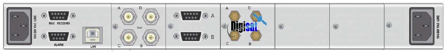
In its default confi guration, the AZ290 only switches an output ASI or G703 (75 ohms) signal. A wide range of input and output switching options makes the AZ290 compatible with almost any signal used in satellite communications. The range of options includes IF and L-band input switches or splitters as well as ASI, optical, G.703, SDH and HSSI output switches.
The AZ290 is easy to operate and monitor. All control and monitoring parameters are available locally on the front panel and remotely through a web interface. It is also possible to control or monitor the AZ290 via RMCP or SNMP.
Key features
• Dual redundant power supply
• Automatic or manual operational mode
• Suitable for any demodulator with alarm contacts
• Switching of IF or L-band inputs
• Switching of ASI, G.703, SDH or HSSI outputs
• DC-pass splitter for direct connection to LNB ( optional)
• Stand alone operation or integrated in a network management system
Main advantages
• Increases service availability signifi cantly
• Compatible with any demodulator that has alarm contacts
• High reliability
• High compactness
• Easy to operate
Applications
• Broadcast satellite contribution
• Primary distribution
• Any downlink facility
Related products
AZ910 DSNG & Contribution Satellite Demodulator
AZ920 Telco Satellite Demodulator
AZ928 High Speed Telco Satellite Demodulator
AZ930 WAN Satellite Demodulator
AZ200 Universal Switching system
AZ210 1+1 Modulator redundancy Switch
AZ270 1+1 Frequency redundancy Switch
Input Interface Splitter
IF splitter
• Connector (in, out) BNC (F) - 75 ohms
• Frequency 40 – 1000 MHz
• Insertion loss < 5dB
• Isolation > 15dB
L-band Splitter
• Connector (in ,out) F (F) – 75 ohms
• Frequency 950 – 2150 MHz
• Insertion loss < 6dB
• Isolation > 15dB
Input Interface Switch
L-band (50 ohms, DC-2.5 GHz)
• Connectors BNC (F) - 50 ohms
• Frequency DC - 2.5 GHz
• Return loss > 18 dB (L band)
• Insertion loss < 0.5 dB
• Isolation > 75 dB (L band)
L-band (75 ohms, DC – 2.5 GHz)
• Connectors BNC (F) – 75 ohms
• Frequency DC – 2.5 GHz
• Return loss > 18 dB
• Insertion loss < 0.5 dB
• Isolation > 75 dB
IF (50 ohms, DC – 270 MHz)
• Connectors BNC (F) - 50 ohms
• Frequency DC - 270 MHz
• Insertion loss < 2 dB
• Isolation > 50 dB ( 300 MHz)
IF (75 ohms, DC - 270 MHz)
• Connectors BNC (F) - 75 ohms
• Frequency DC - 270 MHz
• Insertion loss < 2 dB
• Isolation > 50 dB ( 300 MHz)
Output interface switch
ASI/G.703
• Connectors 4 x BNC (F) - 75 ohms
• Frequency DC - 270 MHz
• Insertion loss < 2 dB
• Isolation > 50 dB ( 300 MHz)
Optical, SC, single mode
• Connector 2 x duplex SC receptacles
• Minimum input power -30dBm
• Minimum output power -15dBm
• Wavelength 1300 nm
• Compliancy SONET OC3 & SDH STM1 (S1.1)
Optical, SC, multi mode
• Connector 2 duplex SC receptacles
• Minimum input power -30dBm
• Minimum output power -23.5dBm
• Wavelength 1300 nm
• Compliancy ATM Forum UNI SONET OC-3 Multimode
Fiber Physical layer specifi cation
HSSI (optional)
• Connectors 25 pin sub-D (F)
• Frequency DC - 52 MHz
• Isolation > 30 dB (balanced)
Generic
Monitor and control interfaces ( via the main unit)
• Web based GUI
• Diagnostics report, alarm log
• RMCP over TCP-IP/UDP and RS232/RS485
• SNMP v2c
Physical
• 1RU, width: 19”, depth 51 cm, 6 kg
• Dual Power supply: 100 - 240VAC, 105 VA, 47-63 Hz
• Temperature
- Operational: 0°C to 37°C
- Storage: -40 to +70°C
• Humidity: 5% to 85% non-condensing
• CE label, UL label
• Broadcast satellite contribution
• Primary distribution
• Any downlink facility