Foxcom Sat-Light L-Band Fiber Optic Link PL7240


Sat-Light Platinum L-band (950-3000 MHz) fiber optic receiver and transmitter.

L-Band PL7240T/PL7240R Fiber Optical Link
Foxcom’s Platinum L-Band products are designed to meet the increasing demand for modularity and high performance in a small form factor for superior long-distance transmission. The link performs at full capability within a 4dB optical budget. High RF input power and wide dynamic range make the link suitable for both Uplink and Downlink applications.
Utilizing Global Foxcom’s DigiRF technology, the user has full control of all important functions for setup, operation, and analysis via the front panel LCD or via the associated sub-rack SNMP capability.
In addition IMizer, an automated adjustable link calibration embedded system enables the user to align the RF links IMD/CNR to specific linearity performances without a two-tone test. Select the desired IMD for the optical transmitter, either locally or remotely, IMizer automatically adjusts the laser drive to meet the IMD requirements.
Each low profile individual transmitter or receiver can be “hot swapped” in the sub-rack chassis maintaining a best subsystem uptime capability. Each module contains an individual processor to maximize specification performance at all times under demanding user applications.
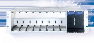
The Platinum transmitter and receiver are designed for sub-rack chassis mounting. The associated Platinum chassis has 12 active slots, one main control processor (MCP) slot and two redundant power supplies. No fans are required even under full sub-rack loading and full LNB powering.
Features & Benefits
- L-Band: 950–3000MHz
- Up to 10Km distance
- Wide input power suitable for both Uplink and Downlink applications
- Powerful management capabilities via a front panel LCD and rack mounted SNMP
- LNB power control via LCD or SNMP: +13 or 18 VDC
- 1550nm and CWDM ITU Grid laser options for longer fiber runs and single fiber CWDM multiplexing solutions
Chassis

Transmitter and Receiver with LCD and LED Indicators
Figure2: Transmitter with LCD and LED Indicators
(Only Transmitter isshown here; Receivers are available and provide corresponding information)

LED Name |
Color |
Description |
| Power | Green | Power On |
| No Light | Power Off | |
| Status/Alarms | Green | No Alarms |
| Amber | Minor Alarms | |
| Red | Critical Alarm | |
| RF Input | Green | Input within specification |
| Amber | Input below specification | |
| Red | No input of above specifications | |
| Remote | Yellow | Main processor control in effect |
| No Light | No main processor control |
SNMP Graphic User Interface (GUI) for Monitoring & Control
Figure3: SNMP GUI

- General data about the system, including version control
- Card status
- Optical power input andoutput monitoring
- RF power input and output monitoring
- AGC/MGCselection
- LNB voltage selection(18V/13V/none)
- IMD selection(TX only)
- Power supply monitoring, such asDC Voltage, AC/DC Failures, Temperature, Fan speed
- Alarm history and alarm severity
- System statistics
Typical L-Band Up and Down Link

Ordering Matrix

Ordering Information
Model Number |
Description |
| PL7240T-50SMA-FC | Sat-Light Platinum L-band (950-3000 MHz) fiber optic Transmitter. Wide RF input (-50 to -5 dBm). 50-Ohm SMA RF connector. FC/APC optical connector. Includes module select LNB power - +13 or +18Vdc. |
| PL7240R4-50SMA-FC | Sat-Light Platinum L-band (950-3000 MHz) fiber optic Receiver. Wide RF output (-40 to -5 dBm). 4dB (8km) optical budget. 50-Ohm SMA RF connector. FC/APC optical connector. |
Recommended Accessories
Active Accessories
- 28dB Gain RF Amp
- 55dB Gain RF Amp
- Redundancy RF Switch
- Optical Ethernet Link
Passive Accessories
- Wideband RF Splitter
- IF RF Splitter
- 10MHz/L-Band Diplexer
- L-Band RF Splitter
- 2way Optical Splitter
- 1310/1550nm MUX/DeMUX
L-Band PL7240T/PL7240R Fiber Optical Link Specifications:
RF Specifications |
Value |
| Frequency Range - Bandwidth | 950–3000MHz |
| Amplitude Response @ Unity Gain 950–3000 MHz any 36 MHz |
±2 ±0.25dB |
| Gain variation over temperature | ±1.5dB |
| Gain stability dB/25hr | ±0.2dB |
| SFDR | >100 dB/Hz |
| Noise Figure (NF) | 20 dB |
| Output IP3 (OIP3) | 20 dBm |
| CNR [any 36MHz] | >57dB |
| Group Delay Variation | <1.5ns |
| Third Order Inter-Modulation [IMD] | -55 to -40dBc |
| RF Input Signal Range – Total Power | -5 to -45dBm |
| RF Output Signal Range – Total Power | -40 to -5dBm |
| TX/RX Input/Output Return Loss 50 Ohm 75 Ohm |
-15dB -13dB |
| RF connector options | N/SMA/F/BNC50/BNC75 |
Optical Specifications |
Value |
| Optical Wavelength | 1310nm |
| Optical Power Output | 2mW / 3dBm |
| Optical Budget / Distance | 4dB/10Km |
| Min RX Optical Input Power | -1dBm |
| Optical Connector Types | FC-APC or SC-APC (E2000 option) |