CPI SAT C240M 2.4M Vehicular Mounted SNG Antenna System


High EIRP, C, X, Ku or Ka-Band Feed Configurations, Ideal for SNG Applications
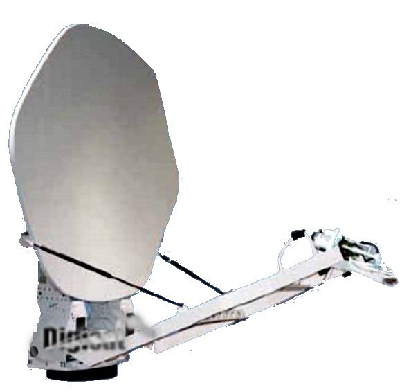
C240M Compact 2.4 Meter Mobile SNG VSAT
The CPI SAT (formerly GD Satcom Technologies & Prodelin) lightweight C240M 2.4m mobile antenna is designed for worldwide transmit and receive operation in C, X, Ku and Ka-band. This mobile antenna consists of a carbon fiber composite reflector and back beam mounted on a cable-driven, elevation-over-azimuth positioning system. This results in an antenna with superior stiffness and high performance under wind loading conditions. The unique shape and the accurate reflector surface provide exceptionally low side lobe and cross-polarization performance, well within INTELSAT and EUTELSAT requirements.
C240M 2.4 METER SINGLE OFFSET MOBILE ANTENNA - Pivot Pallet - Encoder - Single Piece 2.4 m Reflector
- Pivot pallet required for C, X, Ku, and DBS Bands. Required for multifeed applications.
- Elevation over Azimuth, low profile cable drive pedestal designed to be vehicle mounted
- Encoder based motorized drive for Azimuth, Elevation, and Pol
- 30' (10m) control cable with connectors designed for RCI RC3K series controller
- Reflector and Backbeam of carbon fiber
- Antenna feed boom capable of supporting 150 pounds of electronic integration
- Axis crossover/rotary joint sold separately
- Antenna weight 560 pounds
- Stow height 24 inches
- Controller sold separately
- Typical antenna test report available - unit range test sold separately
- Includes Shipping Crate. Dims 131"L x 96"W x 41"H. Weight 1750 lbs typical including antenna, feed, and controller.
- Weight does not include any boom mount RF components or optional equipment.
- Color = Commercial White. 33303 Sand and 34094 Green availab
Quick Feed Re-Configuration
The interchangeable feeds are palletized for quick, easy removal and replacement, allowing the end-user to effectively change frequency bands in the field within minutes.

Mechanical
Azimuth Travel ±150° continuous
Elevation Travel 0° to 90° of reflector boresight
Polarization Travel ±90°
Drive Rates 0.4°/second (azimuth)
0.7°/second (elevation)
2.6°/second (polarization)
Reflector 2.4-meter (94.5 in) carbon fiber composite (single or 3 segment)
Feed Multiband interchangeable
Finish White (standard; other optional finishes also available)
Weight 560 lbs (254 kg) without feed
Stow Height 24 in (61 cm)
Electrical Interface 25 ft (7.6 m) cable, pre-connectorized for various controller options
Integration 150 lbs (68 kg) feed boom mounted
300 lbs (136 kg) positioner mounted
Environmental
Wind Loading¹
Operational 45 mph (72 km/h) gusting to 60 mph (97 km/h)
Survival 45 mph (72 km/h) gusting to 75 mph (121 km/h) any position
90 mph (145 km/h) stow position
Pointing Loss (operational winds) 2.0 dB peak (Ku-band Rx), performance dependent on controller capability
Temperature
Operational -22° to +122° F (-30° to +50° C)
Survival -40° to +158° F (-40° to +70° C)
Rain
Operational 4 in/h (10 cm/h)
Survival 6 in/h (15 cm/h)
Relative Humidity 0% to 100% with condensation
Solar Radiation 360 BTU/h/ft2 (1000 Kcal/h/m2)
Radial Ice (survival) 1 in (25 mm) on all surfaces, 1/2 in (12 mm) on all surfaces with 80 mph (130 km/h) wind gusts¹
Corrosive Atmosphere As encountered in coastal regions and/or heavily industrialized areas
Electrical
|
Frequency (GHz) |
3.625 - |
5.850 - |
3.625 - |
5.850 - |
7.250 - |
7.900 - |
10.950 - |
13.750 - |
10.950 - |
13.750 - |
20.200 - |
30.000 - |
||||||||
|
|
4.200 |
6.425 |
4.200 |
6.425 |
7.750 |
8.400 |
12.750 |
14.500 |
12.750 |
14.500 |
21.200 |
31.000 |
||||||||
|
Antenna Gain at Midband, dBi |
38.20 |
42.00 |
38.06 |
42.10 |
43.50 |
43.60 |
47.19 |
49.00 |
47.10 |
48.80 |
52.30 |
55.20 |
||||||||
|
Antenna Noise Temperature 5° Elevation |
49 K |
|
51 K |
|
68 K |
|
63 K |
|
85 K |
|
143 K |
|
||||||||
|
10° Elevation |
38 K |
|
50 K |
|
59 K |
|
60 K4 |
|
75 K |
|
123 K |
|
||||||||
|
20° Elevation |
33 K |
|
49 K |
|
55 K |
|
56 K |
|
69 K |
|
109 K |
|
||||||||
|
40° Elevation |
34 K |
|
48 K |
|
55 K |
|
55 K |
|
68 K |
|
101 K |
|
||||||||
|
Typical G/T at 4.0 & 7.5 GHz |
|
|
|
|
|
|
|
|
|
|
|
|
||||||||
|
20° Elevation, Clear Horizon C-Band 35° K LNA |
19.5 dB/K |
|
|
|
|
|
|
|
|
|
|
|
||||||||
|
X-Band 55° K LNA |
|
|
|
23.1 dB/K |
|
|
|
|
|
|
|
|||||||||
|
Typical G/T at 4.0 & 10.95 GHz |
|
|
|
|
|
|
|
|
|
|
|
|||||||||
|
10° Elevation, Clear Horizon C-Band 35° K LNA |
|
18.8 dB/K |
|
|
|
|
|
|
|
|
|
|||||||||
|
C-Band 50° K LNA |
|
18.1 dB/K |
|
|
|
|
|
|
|
|
|
|||||||||
|
Ku-Band 70° K LNA |
|
|
|
|
|
25.4 dB/K |
|
|
|
|
|
|||||||||
|
Ku-Band 90° K LNA |
|
|
|
|
|
24.7 dB/K |
|
|
|
|
|
|||||||||
|
Typical G/T at 11.85 GHz |
|
|
|
|
|
|
|
|
|
|
|
|||||||||
|
20° Elevation, Clear Horizon Ku-Band 70° K LNA |
|
|
|
|
|
|
|
25.7 dB/K |
|
|
|
|||||||||
|
Ku-Band 90° K LNA |
|
|
|
|
|
|
|
25.1 dB/K |
|
|
|
|||||||||
|
Typical G/T at 20.70 GHz |
|
|
|
|
|
|
|
|
|
|
|
|||||||||
|
20° Elevation, Clear Horizon Ka-Band 120° K LNA |
|
|
|
|
|
|
|
|
|
28.7 dB/K |
|
|||||||||
|
Ka-Band 200° K LNA |
|
|
|
|
|
|
|
|
|
27.4 dB/K |
|
|||||||||
|
Pattern Beamwidth (in degrees at midband) -3 dB Beamwidth 2.12 |
1.37 |
2.09 |
1.35 |
1.11 |
1.03 |
0.72 |
0.60 |
0.71 |
0.60 |
0.40 |
0.29 |
|||||||||
|
-15 dB Beamwidth 4.45 |
2.88 |
4.39 |
2.84 |
2.33 |
2.16 |
1.51 |
1.26 |
1.49 |
1.26 |
0.84 |
0.61 |
|||||||||
|
Sidelobe Performance3 For Angle A from 2° to 30° (typical) |
|
|
|
29-25 Log A |
29-25 Log A |
29-25 Log A |
||||||||||||||
|
For Angle A beyond |
29-25 Log A |
29-25 Log A |
29-25 Log A |
|
|
|
||||||||||||||
|
mainbeam to 20° |
|
|
|
|
|
|
||||||||||||||
|
For Angle A from 30° to 140° |
|
|
|
|
|
|
-10 dBi |
-10 dBi |
-10 dBi |
-10 dBi |
-10 dBi |
-10 dBi |
||||||||
|
For Angle A from 140° to 180° |
|
|
|
|
|
|
0 dBi |
0 dBi |
0 dBi |
0 dBi |
0 dBi |
0 dBi |
||||||||
|
Cross Polarization On Axis |
30.0 dB |
30.0 dB |
19.7 dB |
27.3 dB |
21.3 dB |
21.3 dB |
35.0 dB |
35.0 dB |
35.0 dB |
35.0 dB |
24.8 dB |
24.8 dB |
||||||||
|
Within 1.0 dB BW |
28.0 dB |
28.0 dB |
19.7 dB |
27.3 dB |
21.3 dB |
21.3 dB |
27.0 dB |
35.0 dB |
27.0 dB |
35.0 dB |
24.8 dB |
24.8 dB |
||||||||
|
VSWR |
1.30:1 |
1.30:1 |
1.30:1 |
1.30:1 |
1.30:1 |
1.30:1 |
1.35:1 |
1.25:1 |
1.35:1 |
1.30:1 |
1.30:1 |
1.30:1 |
||||||||
|
|
(17.7 dB) |
(17.7 dB) |
(17.7 dB) |
(17.7 dB) |
(17.7 dB) |
(17.7 dB) |
(16.5 dB) |
(19.0 dB) |
(16.5 dB) |
(17.7 dB) |
(17.7 dB) |
(17.7 dB) |
||||||||
|
Axial Ratio |
|
|
1.81 dB |
0.75 dB |
1.50 dB |
1.50 dB |
|
|
|
|
1.00 dB |
1.00 dB |
||||||||
|
Port-to-Port Isolation Rx/Tx (Rx frequency) |
0 dB |
-30 dB |
0 dB |
-50 dB |
0 dB |
-110 dB |
0 dB |
-30 dB |
0 dB |
-50 dB |
0 dB |
-50 dB |
||||||||
|
Tx/Rx (Tx frequency) |
-60 dB |
0 dB |
-100 dB |
0 dB |
-110 dB |
0 dB |
-85 dB |
0 dB |
-85 dB |
0 dB |
-85 dB |
0 dB |
||||||||
|
Feed Insertion Loss |
0.15 dB |
0.15 dB |
0.40 dB |
0.20 dB |
0.45 dB |
1.00 dB5 |
0.30 dB |
0.20 dB |
0.60 dB |
0.45 dB |
0.30 dB |
0.30 dB |
||||||||
|
Waveguide Interface Flange |
CPR-229G |
CPR-137G |
CPR-229G |
CPR-137G |
CPR-112G |
CPR-137G |
WR-75 Flat |
WR-75 Flat |
WR-75 Flat |
WR-75 Flat |
WR-42 Flat |
WR-28 Flat |
||||||||
|
Waveguide Interface Az Axis |
|
CPR-137G |
|
CPR-137G |
|
CPR-137G |
|
WR-75 Flat |
|
WR-75 Flat |
|
WR-34 Flat |
||||||||
|
Total Power Handling Capability |
2 kW CW |
2 kW CW |
2 kW CW |
1 kW CW |
2 kW CW |
250 W CW |
||||||||||||||
|
RF Specification |
975-2837 |
975-2712 |
975-10125 |
975-15754 |
975-1708 |
975-2901 |
||||||||||||||
Global Transmit and Receive operation in C-Band, Ku-Band, X-Band and Ka-Band