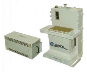
Comtech EF Data SPOD High Power Outdoor SSPA Series Amplifier Systems

Available in C-, X-, or Ku-Band configurations
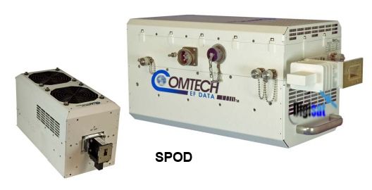
SPOD High Power Outdoor SSPA Series Amplifier Systems
Comtech EF Data’s (CEFD) Series of High-Power Outdoor SPOD C-, X-, and Ku-Band Solid-State Power Amplifiers (SSPA) provide a cost-effective, more reliable replacement for TWT amplifiers in satellite communications terminals. The SPOD delivers its rated power at the 1 dB compression point, to the transmit waveguide flange.
The Solid State Advantage
Each SPOD SSPA is constructed with highly reliable GaAs FETs. With third order intermodulation products from 4 to 6 dB better than TWT ratings, the CEFD unit has the ability to replace TWTs with saturated power levels of up to twice the SPOD’s rated output.
Functional Description
A SPOD consists of an SSPA module with the Monitor/Control Processor (MCP), an integrated power supply, and a field replaceable fan assembly. The amplifier features a Comtech EF Data low loss combining technique and MCP-based temperature versus gain compensation.
Feature Packed
The SPOD SSPAs are equipped with useful features that other manufacturers offer as options. Included in each unit’s base price are temperature compensation, sample ports, power monitor, power factor corrected supply and full remote monitor and control capabilities, including Ethernet HTTP pages and SNMP.
Redundancy
Another challenge addressed by the SPOD topology is the increasing need for redundant RF solutions. With a unique solution to system control, The SPOD offers a very cost-effective solution for 1:1 redundant TX requirements.
Integrated Power Supply
All SPOD SSPAs have a self-contained, extremely rugged, power supply. While generally fielded as an AC powered unit, SPODs are also available with -48 VDC power supplies.
Data Logging Capability
To greatly enhance system maintainability, the SPOD line includes a built in data logging capability. By recording critical operational parameters (such as temperature, output power, mute status, etc.) at time stamped intervals, the user can quickly gather intelligence not only about the unit itself, but also the unit’s operational environment.
RF Output Frequency
5.850 – 6.425 GHz
5.850 – 6.650 GHz (optional)
5.850 – 6.725 GHz (optional)
6.725 – 7.025 GHz
7.900 – 8.400 GHz
14.00 – 14.50 GHz
13.75 – 14.50 GHz (optional)
Model Psat (Typical) P1dB
(Guaranteed)Note 1
PS1-20Ku 43 dBm (20 W) 42 dBm (16 W)
PS1-32Ku 45 dBm (32 W) 44 dBm (25 W)
PS1-40Ku 46 dBm (40 W) 45 dBm (32 W)
PS1.5-50Ku 47 dBm (50 W) 46 dBm (40 W)
PS1.5-60Ku 48 dBm (60 W) 47 dBm (50 W)
PS2-100Ku 50 dBm (100 W) 49 dBm (80 W)
PS2-125Ku 51 dBm (125 W) 50 dBm (100 W)
PS1-32C,X 45 dBm (32 W) 44 dBm (25 W)
PS1-50C,X 47 dBm (50 W) 46 dBm (40 W)
PS1-60C,X 48 dBm (60 W) 47 dBm (50 W)
PS1.5-80C,X 49 dBm (80 W) 48.5 dBm (70 W)
PS1.5-110C,X 50.4 dBm (110 W) 49.5 dBm (90 W)
PS1.5 or PS2-125C,X 51 dBm (125 W) 50 dBm (100 W)
PS2-150C,X 51.8 dBm (150 W) 51 dBm (125 W)
PS2-200C,X 53 dBm (200 W) 52.5 dBm (175 W)
PS2-250C,X 54 dBm (250 W) 53 dBm (200 W)
Input Power Supply Requirements: 90 – 264 VAC, 47-63 Hz,
Power Factor Corrected, .96 (48 VDC optional)
|
Gain Min. (Typical) All power levels |
70 (75 dB) |
|
Max. Input level (no damage ) |
+10 dBm |
|
Gain Adjust |
20 dB in 0.25 dB steps |
|
Gain Flatness |
± 1.5 dB full band (optional ± 2.0 dB full band (-50 to +55C)) ± 0.30 dB per 40 MHz (optional ± 0.50 dB per 40 MHz (-50 to +55C)) |
|
Gain variation over temp |
±1.5 dB max., -40 to +55 °C (optional ± 2.0 dB max. (-50 to +55C)) |
|
Input Return Loss |
19.1 dB (1.25:1 VSWR) |
|
Output Return Loss |
19.1 dB (1.25:1 VSWR) |
|
Noise Figure |
8-10 dB typ., 15 dB max. @ min. attenuation, |
|
RF Mute Isolation |
60 dB min. |
|
AM/PM Conversion |
2° typ., 3.5° max. @ Rated P1dB |
|
3rd Order Intermod. Level (2 tones, @ -3 dB Total Back Off from P1 dB (-6 dBc SCL), Δ 1 MHz) |
-30 dBc typ., -25 dBc Guaranteed |
Spurious Level |
|
|
Harmonics |
-50 dBc @ Prated -3dB |
|
Non-Harmonic Related |
-65 dBc max. |
|
Group delay variation Notes: 1. Allow 1 dB degradation from 13 |
Linear ± 0.03ns/MHz Parabolic ± .003ns/MHz2 Ripple ± 1.0 ns pk-pk .75 to 14.0 GHz and 6425 to 6725 MHz |
|
Data Logging parameters |
Non-Volatile RAM : Capacity 30 days @ 90 minute intervals Includes: RF Output Power Mute Status Heatsink Temperature |
|||
|
|
||||
Environmental & PhysicalTemperature |
||||
|
Operating |
-40º to 122ºF (-40º to 55ºC) (optional -50 to 55C or -40 to +60ºC) |
|||
|
Storage |
-67º to 167ºF (-55º to 75ºC) |
|||
|
Humidity |
100% condensing rain 2” per hour |
|||
|
Altitude |
10,000 AMSL (derate 2ºC/1000 ft. AMSL) |
|||
|
Shock |
Normal commercial shipping and handling |
|||
|
Weight / Dimensions (height x width x depth (in. excluding connectors)) |
||||
|
PS1,1.5 |
17 lbs Nominal |
/ |
7.37” x 6.26” x 12.65” |
|
|
PS2 |
47 lbs Nominal |
/ |
9.78” x 8.80” x 16.81” |
|
|
Connectors |
|
|
||
|
RF Input |
Type N, female |
|
|
|
|
RF Output |
PS1, C-Band: Type N, female |
|||
|
PS1.5/PS2, C-Band: CPR137G |
||||
|
PS1/1.5/PS2 X-Band: CPR112G |
||||
|
PS1/1.5/PS2 Ku-Band: WR75G |
||||
|
M&C/Ethernet/ Redundancy Switches |
19-pin MS Style (Single Integrated cable assembly available, dependent upon configuration) |
|||
Video Broadcast, Satellite Teleports, Military Communications, Internet Access Services, Disaster communications, Telco Restoral Services