Teledyne Paradise Datacom 4RU C-Band Compact Indoor Rack Mount Solid State Amplifier (SSPA) Systems


Highest possible MTBF's, Power output available up to 600 Watts

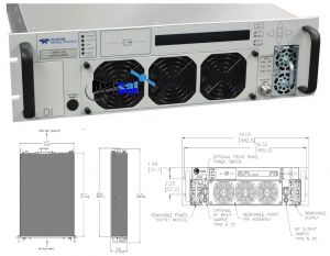
4RU C-Band Compact Indoor Rack Mount Solid State Amplifier (SSPA) System
Teledyne Paradise Datacom’s Indoor, Rack Mount (R) series SSPAs represent the latest in High Power Microwave Amplifier Technology. The 4RU SSPA chassis achieves the highest power density in the industry along with enhanced maintainability. Local, front panel, control is available with a user friendly interface. Five fault condition LEDs on left side of the front panel reflect some of the SSPA major faults states, plus a summary fault indicator. The SSPA online LED turns green when the amplifier is in Online mode (1:1 Mode) or serves as an AC power indicator in standalone mode. Local/Remote and Mute/ Unmute LEDs show the current control mode and mute state of the amplifier.
A full compliment of serial and parallel (contact closure) control is also available from the rear panel. Teledyne Paradise Datacom’s Windows based Universal M&C software allows monitor and control of the SSPA from a remote computer.
A state of the art thermal platform provides efficient cooling for the amplifier module and power supplies. This ensures the highest possible MTBFs for microwave power amplifiers.
Along with high reliability comes the ultimate in amplifier maintainability. Amplifier modules and power supplies are easily accessed making this one of the easiest amplifier assemblies to maintain in the field.
4RU System Features:
Extremely High Power Density:
- S Band to 600W
- C Band to 600W
- X Band to 500W
- Ku Band to 250W
Removable Fan Trays
Removable M&C Card
RF Output Sample Port (-40 dB)
RF Gain Adjustment 55 dB - 75 dB
Ethernet Port x Universal
Power Factor Corrected Power Supply
Built-in 1:1 Redundancy Control
Paradise SSPA OPTIONS:
N+1 Redundant Power Supply
Extended Frequency Bands
L-Band Input operation
ZBUCTM converter
Reflected Power Monitor
Phase Combined Systems
Input Sample Port
Exhaust Duct Adapters
Redundant and Phase Combined System Solutions
|
Common Electrical Specifications PARAMETER |
NOTES |
LIMITS |
UNITS |
|
Gain Gain Flatness Gain Slope Gain Variation vs. Temperature Gain Adjustment |
minimum full band Extended C-Band units per 40 MHz (C, X, Ku) Per 10 MHz (S-band) 0°C to +50°C 0.1 dB resolution |
75 ±1.0 ±1.5 ±0.3 ±0.2 ±1.0 20 |
dB dB dB dB/40 MHz dB/10 MHz dB dB |
|
Intermodulation Distortion |
3dB back off relative to P1dB |
-25 |
dBc |
|
AM/PM Conversion |
(@ rated P1dB) (@P1dB-3dB) |
3.5 1.0 |
o/dB o/dB |
|
Spurious Harmonics |
(@ rated P1dB) (@ rated P1dB-3dB) (C-,X-,Ku-bands) (@ rated P1dB-3dB) (S-Band) |
-70 -50 -40 |
dBc dBc dBc |
|
Input/Output VSWR |
All units except Extended C-Band Extended C-Band units |
1.30:1 1.50:1 |
|
|
Noise Figure |
at maximum gain |
12 |
dB |
|
Group Delay |
Linear Parabolic Ripple |
0.01 0.003 1.0 |
ns/MHz ns/MHz2 ns p-p |
|
Noise Output |
TX Band (S, C-, X- or Ku-Band) RX Band (C- or Ku-Band) RX Band (X-Band) RX Band (S-Band; see page 2) |
-75 -150 -100 |
dBW/4 KHz dBW/4 KHz dBW/4 KHz |
|
Residual AM Noise |
0 - 10 KHz 10 KHz - 500 KHz 500 KHz - 1 MHz |
-45 -20 (1.25 + log F) -80 |
dBc dBc dBc |
|
Residual Phase Noise |
Offset frequency from carrier 10 Hz 100 Hz 1 KHz 10 KHz 100 KHz 1 MHz |
-90 -100 -110 -120 -125 -130 |
dBc/Hz dBc/Hz dBc/Hz dBc/Hz dBc/Hz dBc/Hz |
|
Connectors |
RF Input, Input & Output Sample RF Output: HPAS2XXXRXXXXX RF Output: HPAC2XXXRXXXXX RF Output: HPAX2XXXRXXXXX RF Output: HPAK2XXXRXXXXX Line Power |
Type N Type N WR137 Waveguide WR112 Waveguide WR75 Waveguide (90-265) IEC 6100-3300 (180-265) IEC 4798-9000 |
Female Female CPR137G Flange (PDR-70) CPR112G Flange (PDR-84) Grooved Flange (PBR-120) Plug Plug |
Scientific research missions, Telemetry, Government Communications