Newtec Azimuth Series AZ720 L-Band Downconverter
Internal 10 MHz reference, High Stability Frequency Conversion
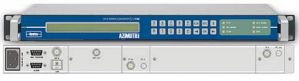
AZ720 L-Band to IF Downconverter
This product has reached end of life and has been replaced by the Newtec FRC0720
The Newtec Azimuth AZ720 is a high performance L-band to IF frequency downconverter designed for a wide range of broadcast, telco and IP satellite applications. The AZ720 offers some advanced and unique features such as a calibrated high linearity over the entire bandwidth combined with a very high frequency stability.
The AZ720 has a very wide gain range and a low noise figure which makes it suitable for the conversion of narrow and broadband L-band signals to IF. The L-band input frequency is adjustable over the range of 950 MHz up to 2150 MHz. The IF output frequency is switchable between 70 MHz and 140 MHz.
The high output frequency stability is provided by an internal 10 MHz reference clock. For applications requiring a very high frequency stability such as very low data rate carriers, an optional reference clock of 0,01ppm can be ordered separately.
Built-in LNB Power
Optionally, an LNB power supply, a frequency band selection signal and a 10MHz reference frequency can be delivered to an LNB via the L-band input providing a compact and cost effective solution.
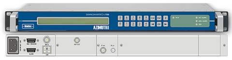
The AZ720 is easy to operate and monitor. All control and monitoring parameters are available locally on the front panel and remotely through a web interface. It is also possible to control or monitor the AZ710 via RMCP or SNMP.
Key features
![]() Agile L-band to IF-band downconverter
Agile L-band to IF-band downconverter
![]() High Gain
High Gain
![]() IF output frequency switchable between 70 and 140 MHz
IF output frequency switchable between 70 and 140 MHz
![]() Ultra fine L-band frequency resolution (48Hz)
Ultra fine L-band frequency resolution (48Hz)
![]() Very high frequency stability
Very high frequency stability
![]() High linearity over the entire bandwidth
High linearity over the entire bandwidth
![]() Low noise figure
Low noise figure
![]() Spectrum inversion
Spectrum inversion
![]() LNB power supply
LNB power supply
![]() 10 MHz reference input/output
10 MHz reference input/output
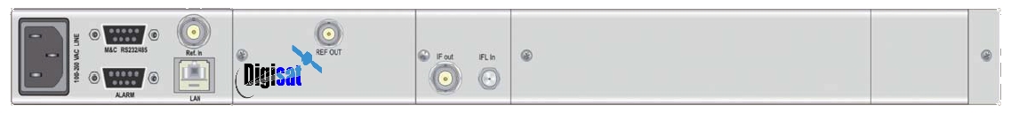
Interfaces
Input interface (IF)
• Connector SMA (F), 50 ohms
• Return loss >15dB
• Frequency range 950 to 2150 MHz
• Input level Max composite -20dBm
Output interface (IF)
• Connector BNC (F), 50 ohms
• Return loss >15dB
• Frequency range 70 ± 20MHz,
140 ± 40MHz
• Output level <=0 dBm typical
10 MHz reference input / output
• Connector BNC (F), 50 ohms
• Input level -3dbm up to 7dBm
• Output level +7dBm
LNB power and control (optional)
• max. current 350 mA (on L-band input)
• voltage 11,5 -14 V (Vertical polarization) 16 -19 V (Horizontal polarization) & additional 22 kHz +/- 4KHz (band selection according to universal LNB)
• 10 MHz reference
Transfer characteristics
Gain
• Programmable Gain 0 to 50 dB
• Gain step size 0.1 dB
• Gain variation over 36/72 MHz BW 1.2 dB
peak-to-peak
• Gain variation over T°(+20 to +40°C) ± 0.5 dB
Linearity
• Output 1dB compression IF +10dBm
• AM/PM conversion 0.1°/dB
max@0dBm
output
Switching
• Spectrum inversion Selectable
• Output switching suppression >80 dB
Noise
• In band spurious (signal related) <-60 dBc
(@ -25 dBm
input and
0 dBm output)
• Non signal related spurious <-70dBm
• Image rejection -60dBc
• Noise fi gure <15 dB
at max gain
• Phase noise
@ 10 Hz <-50 dBc/Hz
@ 100 Hz <-70 dBc/Hz :
@ 1KHz <-80 dBc/Hz
@ 10 KHz <-85 dBc/Hz
@ 100 KHz <-95 dBc/Hz
• Group delay:
@ 72 MHz BW @ 36 MHz BW
Linear group delay 0.05 ns/MHz 0.03 ns/MHz
Parabolic group delay 0.0035 ns/MHz2 0.01 ns/MHz2
Residual group delay 1 ns peak-to-peak 1 ns peak-to-peak
10 MHz Internal Reference
Frequency
High Stability
Stability: ±5x10⁻⁸ over 0°C to 70°C
Ageing: ± 15 ppb/day
± 300 ppb/year
Very High Stability (optional)
Stability: ±2x10⁻⁹ over 0°C to 65°C
Ageing: ± 0.5 ppb/day
± 500 ppb/10 year
Available Alarms
• 10 MHz alarm
• Power supply alarm
• Temp. alarm
• Synthesizer out-of-lock
• Input Overload warning (no Rx switch-off ) (adjustable & selectable threshold)
• Input underload alarm (adjustable & selectable threshold)
Generic
Monitor and control interfaces
• Web based GUI
• Diagnostics report, alarm log
• RMCP over TCP-IP/UDP and RS232/RS485
• SNMP v2c
Alarm interface
• Electrical dual contact closure alarm contacts
• Connector 9-pin sub-D (F)
• Logical interface and general device alarm
Physical
• 1RU, width: 19”, depth 51 cm, 6 kg
• Power supply: 90-130 & 180-260 Vac, 105 VA, 47-63 Hz
• Temperature
- Operational: 0°C to 40°C
- Storage: -40 to +70°C
• Humidity: 5% to 85% non-condensing
• CE label
• Earth Stations
• Telco and trunking infrastructure
• Generic satcom applications