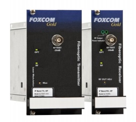
Foxcom Sat-Light C-Band Tx/RX Fiberoptic Interfacility Links


Optical C-Band transmit and receive from 3.4 to 6.8 GHz, fully transparent link
C-Band Tx/RX Fiberoptic Interfacility Links
Foxcom’s Sat-Light C-Band fiberoptic interfacility links transmit and receive uplink and downlink signals in the 3.4 to 6.8 GHz range
between antennas and control rooms or NOCs. Foxcom’s IFLs offer a high performance alternative to conventional coaxial-cabled
systems, reducing the need for waveguide and minimizing signal attenuation.
Fully Transparent
The Sat-Light IFLs function as a transparent link, transmitting all satellite modulation formats carrying an entire polarization on each
link. System limitations in using coaxial cable are overcome by the simplicity and performance of fiberoptic connections to provide
the highest levels in signal quality. Foxcom achieves this by using state of the art lasers to provide these high efficiency, low noise
analog links.
Overview
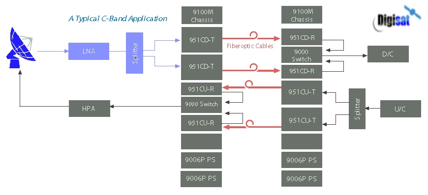
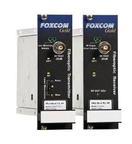
A typical C-Band link consists of an optical transmitter, which receives the RF signal, transmitting it over singlemode fiber to an
optical receiver which reconverts the optical signal to RF. Foxcom’s advanced fiberoptic technology reduces the attenuation, slope,
phase shift, and group delay, maintaining extremely low levels over distances of up to 15 kilometers. The C-Band’s link state of
the art lasers produce negligible chirp and optical distortion; critical for long distance links. The links are
provided with test ports, status and fault LEDs, and gain controls.
GL952CU C-Band Optical Uplink
Features & Benefits
Optimized for Professional Satellite Applications
15Km Transmission Distance
Transmitter and Receiver Gain Control
Front Panel Test Port
Powerful Monitoring Features
Compatible with all 1st Generation SatLight Products
Foxcom's Sat-Light C-Band fiberoptic interfacility links transmit and receive uplink signals in the 5.8─6.8 GHz range between antennas and control rooms or NOCs. Foxcom's IFLs offer a high performance alternative to conventional coaxial-cabled systems, reducing the need for waveguide and minimizing signal attenuation. C-Band Uplink Datasheet
GL952CD C-Band Optical Downlink
Features
Frequency from 3.4 to 4.2 GHz
Adjustable Link Gain
Input/Output Impedance: 50 Ohm
TX/RX Input/Output VSWR @50 Ohm = 1.5:1
Ordering Information
GL952CD-T ─ Gold C-Band Downlink Transmitter
GL952CD-R ─ Gold C-Band Downlink Receiver
Extremely Low Loss
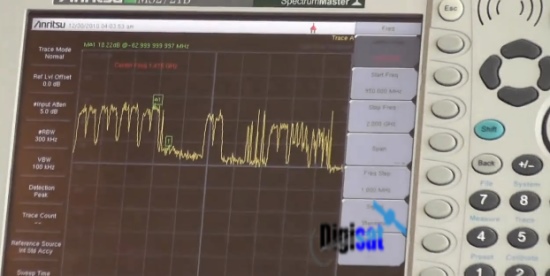
Satellite Markets- Fiber Optic IFL System Overview with Digisat's CEO
Whether your requirements are for a single pre-engineered fiber optic IFL system or a fully engineered solution, Digisat can deliver a total turnkey solution including installation, integration and testing.
Optical Specifications
|
Optical Wavelength |
1550 nm (DWDM optional) |
|
Optical Power Output |
-3 dBm (typical) |
|
Optical Connector |
FC/APC |
|
Optical Budget |
4 dB (15 km) |
|
Optical Return Loss |
-60 dB all connectors |
|
|
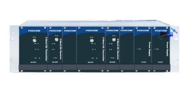
C Band Downlink TX Model 951CD-T RX Model 951CD-R |
C-Band Uplink TX Model 951CU-T RX Model 951CU-R |
|
Parameter |
Typical Downlink Specs |
Typical Uplink Specs |
|
Frequency Range |
3400 - 4200 MHz |
5800 - 6725 MHz |
|
Flatness |
± 0.25 dB / 48 MHz ± 0.75 / 500 MHz |
± 0.25 dB / 48 MHz ± 0.75 dB / 500 MHz |
|
Input/Output VSWR |
<1.5:1 |
< 1.5:1 |
|
Intermodulation* |
> -50 dBc |
> -50 dBc |
|
CNR (48 MHz BW) |
>45 dBc |
>45 dBc |
|
Input Signal Range |
-5 to -25 dBm |
-5 to -20 dBm |
|
Output Signal Range |
-5 to -25 dBm |
-5 to -20 dBm |
|
Gain Stability @ Constant Temp |
± 0.15 dB / 24 hours |
± 0.15 dB / 24 hours |
|
Link Gain |
0 dB adjustable |
0 dB adjustable |
|
OIP3 (@ max gain) |
+15 dBm typical |
+20 dBm typical |
|
Noise Figure @ max input gain |
<23 dB |
28 dB |
|
Group Delay Variation: Peak to peak |
0.3 ns |
0.4 ns |
|
Input/Output Impedance |
50 Ohm |
50 Ohm |
|
Maximum RF Input with no damage |
+5 dBm for 60 seconds |
+5 dBm for 60 seconds |
|
Gain Control |
Manual front panel - standard (Fixed gain or AGC optional) |
Manual front panel - standard(Fixed gain or AGC optional) |
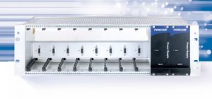
Physical Specifications
|
Chassis Size & |
8 receivers or 4 transmitters max. |
|
|
Capacity |
|
|
|
Chassis |
19" 3U standard format |
|
|
Unit Size |
Receiver 5"x 5" x 1.5" |
|
|
Transmitter 5" x 5" x 3" |
|
|
|
RF Connector |
SMA |
|
|
Power for Transmitter |
8 W |
|
|
Power for Receiver |
2.6 W |
|
|
Operating Temp. Range |
-10 to 55 o C |
|
|
Storage Temp. Range |
-30 to 75o C |
|
Ordering Information
|
C Band U/L TX |
951CU-T |
|
C Band U/L RX |
951CU-R |
|
C Band D/L TX |
951CD-T |
|
C Band D/L RX |
951CD-R |
All C-Band Satellite Communications Systems applications including teleports, VSAT terminals, military, video broadcasting and more