Comtech EF Data MBT-4000 Frequency Converter Multi-Band RF Transceiver


Available in C, X, Ku or Ka-band frequencies
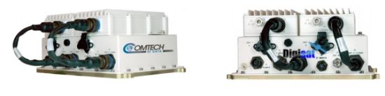
MBT-4000 Frequency Converter Multi-Band RF Transceiver
The RF marketplace has been transitioning from traditional 70/140 MHz IF-based networks to systems using L-Band (950 to 2000 MHz) for the modem/RF equipment link. The Comtech MBT-4000 and MBT-4000B Multi-Band RF Transceivers are designed to perform C, X, Ku or Ka RF to L-Band down conversion and L-Band to C, X, Ku or Ka RF up conversion. The MBT-4000 supports two independent converter modules. The MBT-4000B supports one up converter module and also provides the bias, reference, and monitoring of one LNB.
The transceivers also provide the following features:
• RF band switching in minimal time without requiring tools
• Minimal cost for a complete system including spares
• Easy expansion for providing a redundant system or other frequency bands
• Rugged construction for mobile and transportable applications
• Automatic band identification for the BUC, BDC, and antenna feed (if the feeds provide an identifying connector)
• Meets or exceeds MIL-STD-188-164A
• Low phase noise
• No spectral inversion
• 10 dB gain adjustment
• Auto band sensing capability
• Easy system status verification via LEDs located behind a removable cover
• 1:1 redundant up and down conversion which can be “Chain switched” with external amplifiers and LNA/LNBs
Applications
The flexibility of the MBT-4000 & MBT-4000B make them ideally suited for:
• Earth stations where L-Band IF products are being integrated into a 70/140 MHz IF infrastructure
• Reconfigurable multi-band requirements that are typically found in transportable / flyaway type installations
BUC-4000 ODU
|
Input Frequency Range |
950 to 2000 MHz |
|
Output Frequency By Model: |
|
|
BUC-4000C |
5860 - 6650 MHz |
|
BUC-4000X |
7900 - 8400 MHz |
|
BUC-4000Ku |
13.75 - 14.50 GHz |
|
BUC-4000Ka |
30.00 - 31.00 GHz |
|
Input/Output Impedance |
50O |
|
Input Return Loss |
15 dB minimum |
|
Output Return Loss |
18 dB minimum |
|
Input Connector |
Type - N, female |
|
Output Connector |
N, Female (C-, X-, and Ku-Band) |
|
Gain |
15 dB nominal at min attenuation |
|
User Attenuation Range |
0 t0 10 dB |
|
Output Power, P1dB |
+10 dBm minimum |
|
Third Order Intercept |
+20 dBm minimum |
|
Carrier Spurious |
-60 dBc |
|
Non-Carrier Spurious |
-60 dBm |
|
External Reference |
Input, either 5 or 10 MHz ±5 dBm optional |
UCS-4000 Combined Transfer Characteristics |
|
|
Gain |
40 dB nom at minimum attenuation |
|
Gain Adjustment |
50 dB, 0.25 dB steps (0.1 dB opt) |
|
Gain Adjustment Accuracy |
1.0 dB over 50 dB range |
|
Gain Stability |
±0.25 dB/day at constant temperature |
|
Noise Figure |
20 dB at minimum attenuation |
|
AM/PM Conversion |
0.1 deg/dB, max, to -5 dBm output |
|
Group Delay: |
|
|
Linear |
±0.05 ns/MHz |
|
Parabolic |
±0.01 ns/MHz2 |
|
Ripple |
1 ns p-p |
|
Third Order Intercept |
+20 dBm |
|
Amplitude Response |
±0.50 dB over any 36 MHz (72 MHz) ±1.1 dB over full band |
BDC-4000 Block Down Converter ODU |
|
|
Input Frequency By Model: |
|
|
BDC-4000C |
3400 to 4200 MHz |
|
BDC-4000X |
7250 to 7750 MHz |
|
BDC-4000K |
10.95 to 12.75 GHz |
|
BDC-4000Ka |
20.20 to 21.20 GHz |
|
Output Frequency Range |
950 to 2000 MHz |
|
Input/Output Impedance |
50O |
|
Input Return Loss |
18 dB minimum |
|
Output Return Loss |
15 dB minimum |
|
Input Connector |
N, Female (C-, X-, and Ku-Band) |
|
Output Connector |
N, Female |
|
Gain |
15 dB nominal at minimum attenuation |
|
User Attenuation Range |
0 to 10 dB, in 0.25 dB steps (0.1 dB opt) |
|
Output Power, P1dB |
+ 10 dBm minimum |
|
Third Order Intercept |
+ 20 dBm minimum |
|
Carrier Spurious |
-60 dBc |
DCS-4000 Combined Transfer Characteristics |
|
|
Gain |
50 dB nom at minimum attenuation |
|
Gain Adjustment |
50 dB, 0.25 dB steps (0.1 dB opt) |
|
Gain Adjustment Accuracy |
1.0 dB over 30 dB range |
|
Gain Stability |
±0.25 dB/day at constant temperature |
|
Transmit Phase Noise |
Exceeds requirements of MIL-STD 188-164A |
|
Noise Figure |
15 dB max, at minimum attenuation |
|
Image Rejection |
60 dB minimum |
|
AM/PM Conversion |
0.1 deg/dB, max, to -5 dBm output |
|
Group Delay: |
|
|
Linear |
±0.05 ns/MHz |
|
Parabolic |
±0.01 ns/MHz2 |
|
Ripple |
1 ns p-p |
|
Third Order Intercept |
+20 dBm minimum |
|
Amplitude Response |
±0.50 dB over any 36/72 MHz |
Environmental and Physical |
|
|
Operating Temperature: |
|
|
Operating Humidity |
5 to 95% non-condensing |
|
Operating Altitude |
10,000 ft above sea level |
|
Non-Operating Temperature: |
-50° to +71°C(58° to 160°F) |
|
Prime Power |
90 to 260 VAC, 47 to 63 Hz |

The flexibility of the MBT-4000 & MBT-4000B make them ideally suited for: • Earth stations where L-Band IF products are being integrated into a 70/140 MHz IF infrastructure • Reconfigurable multi-band requirements that are typically found in transportable / flyaway type installations