Quintech Electronics QRM 1000 16X16 Broadband RF Routing Matrix Switch
Frequency range covers Broadband 50-1000MHz, IF 50-200MHz or L-band 950-2150MHz
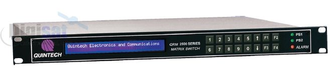
QRM 1000 16x16 Broadband RF Routing Matrix Switch
This product has reached end of life and is no longer available. Please contact us for a replacement solution.
The highly versatile Quintech Electronics QRM 1000 (QRM100016x16CFFA600) is a full fan-out RF matrix switch that can be fully populated as a 16x16. Available in 1 RU as 8x8, 8x16, 16x8 and 16x16. The 8x8 can be expandable to full 16x16 with purchase of access code. The QRM can be easily expanded to a maximum system size of 32x32 by adding additional modules. The QRM features Quintech’s latest Q-ROUTE™ and Q-SENSE™ technology, which provides maximum reliability with signal path redundancy and auto re-route capabilities. The QRM’s operating frequency range covers L-band, IF and Broadband. It also offers manual and AGC modes. It is controllable either locally via the front panel keypad or remotely over Ethernet and is compatible with most monitoring and control systems.
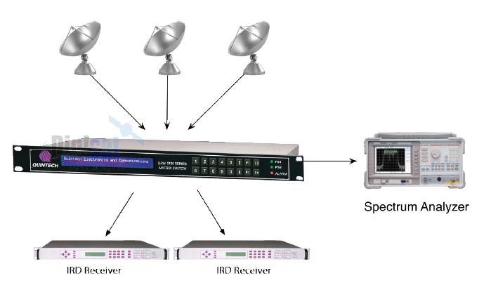
Full Fan Out Matrix Switch System shown here with the Quintech QRM 1000
Benefits
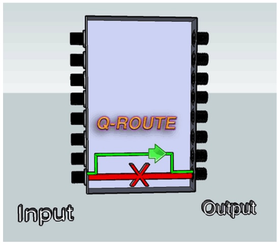
Q-ROUTE Provides Internal Signal Path Redundancy by Automatically Re-routing Around a Failed Signal Path
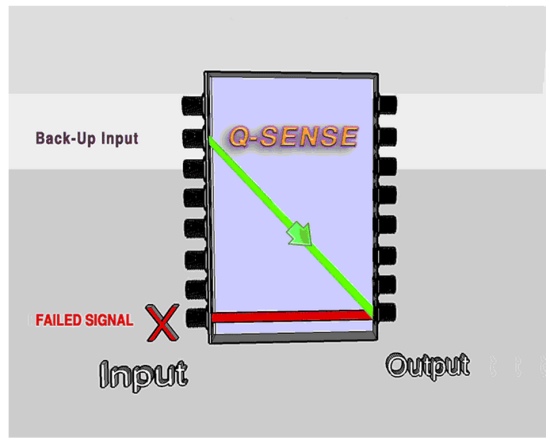
Q-SENSE Provides External Signal Path Redundancy by Automatic Switching of Back-up Input Signals
Quintech QRM 1000 Features
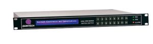
![]() Compact Design - 16x16 in 1RU
Compact Design - 16x16 in 1RU
![]() Operating Frequencies covers Broadband 50-1000MHz, IF 50-200MHz or L-band 950-2150MHz
Operating Frequencies covers Broadband 50-1000MHz, IF 50-200MHz or L-band 950-2150MHz
![]() Full fan-out switching
Full fan-out switching
![]() Manual Gain & AGC modes with a range of -15 dB to +16 dB in 0.5 dB step
Manual Gain & AGC modes with a range of -15 dB to +16 dB in 0.5 dB step
![]() Remotely controlled via web browser interface, Ethernet orTelnet via customer supplied PC
Remotely controlled via web browser interface, Ethernet orTelnet via customer supplied PC
![]() Re-configure signal paths in milliseconds
Re-configure signal paths in milliseconds
![]() Q-ROUTE Provides internal signal path redundancy by automatically re-routing around a failed signal path
Q-ROUTE Provides internal signal path redundancy by automatically re-routing around a failed signal path
![]() Q-SENSE Provides external signal path redundancy by automatic switching to a back-up input signal, if alternate is selected
Q-SENSE Provides external signal path redundancy by automatic switching to a back-up input signal, if alternate is selected
![]() QRP Matrix Combining Module Part # QRP250016AGFB000 QRP Passive Input/Output Module
QRP Matrix Combining Module Part # QRP250016AGFB000 QRP Passive Input/Output Module
|
*Specifications: |
L-band |
IF |
Broadband |
|
Operating Frequency: |
950-2150 MHz |
50-200 MHz |
50-1000 MHz |
|
Configurations: |
8x8 up to 32x32 |
8x8 up to 32x32 |
8x8 up to 32x32 |
|
Frequency Response: |
± 1.5 dB ± 0.4 dB Over any 36 MHz channel |
± 2.25 dB ± 0.6 dB Over any 36 MHz channel |
± 2 dB ± 0.6 dB Over any 36 MHz channel |
|
Isolation: |
65 dB Input to Input 60 dB Output to Output 50 dB Input to Output |
65 dB Input to Input 60 dB Output to Output 55 dB Input to Output |
60 dB Input to Input 60 dB Output to Output 45 dB Input to Output |
|
RF Input Power : |
-10 dBm to -70 dBm |
-10 dBm to -70 dBm |
-10 dB to -70 dB |
|
Gain Range (Manual mode): |
-15 dB to +16 dB in 0.5 dB Steps |
-15 dB to +16 dB in 0.5 dB Steps |
-15 dB to +16 dB in 0.5 dB Steps |
|
RF Sensing and AGC Range: |
-10 dBm to -50 dBm |
-10 dBm to -50 dBm |
-10 dBm to -50 dBm |
|
Input P1dB: |
+2 dBm |
-3 dBm |
-2 dBm |
|
OIP3: |
+10 dBm |
+8 dBm |
8 dBm |
|
Input Return Loss : |
+14 dB |
+14 dB |
+ 14 dB |
|
Output Return Loss: |
+14 dB |
+14 dB |
+ 14 dB |
|
Noise Figure : |
<18 dB @ 0 dB <9.5 dB @ 16 dB |
<18 dB @ 0 dB <9.5 dB @ 16 dB |
<20 dB @ 0 dB <11 dB @ 16 dB |
|
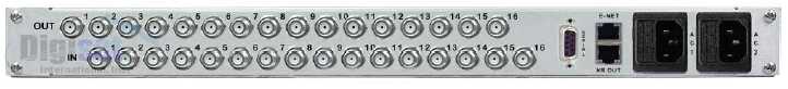
RF Connectors: |
BNC (50 or 75 Ω), Type “F”, SMA Connectors, Contact Digisat for options |
BNC, 50 or 75 Ω), Type “F” |
|
|
Impedance: |
50 Ω or 75 Ω |
50 Ω or 75 Ω |
50 Ω or 75 Ω |
|
AC Input Power: |
Auto ranging 100-240 VAC, 50/60 Hz |
||
|
Local Control: |
Front Panel Keypad with LCD Display |
||
|
PC Remote Control: |
RS-232, RS-485, SNMP, TELNet or TCP/IP via Customer Supplied PC, Web Browser Control |
||
|
Software: |
Basic PC-compatible Software and Command Protocol Included |
||
|
Mechanical: |
16 x 16 in 1RU: 1.75”H x 19”W x 18.5”D |
||
|
Power Consumption: |
80W |
||
|
Weight: |
14.5 lbs. Gross (boxed), 12.0 lbs. Net |
||
Satellite uplink and downlink systems for video or data, RF Matrix Switching Applications